Nissan Pathfinder (2011 year). Manual - part 77


  Index      Manuals     Nissan Pathfinder (2011 year) - Service and Repair Manual


Search            copyright infringement  


Content      ..     75      76      77      78     ..


Nissan Pathfinder (2011 year). Manual - part 77


AV

STEERING SWITCH

AV-435

< REMOVAL AND INSTALLATION >

[BOSE AUDIO WITH NAVIGATION]

C

D

E

F

G

H

I

J

K

L

M

B

A

O

P

STEERING SWITCH

Removal and Installation

INFOID:0000000006246816
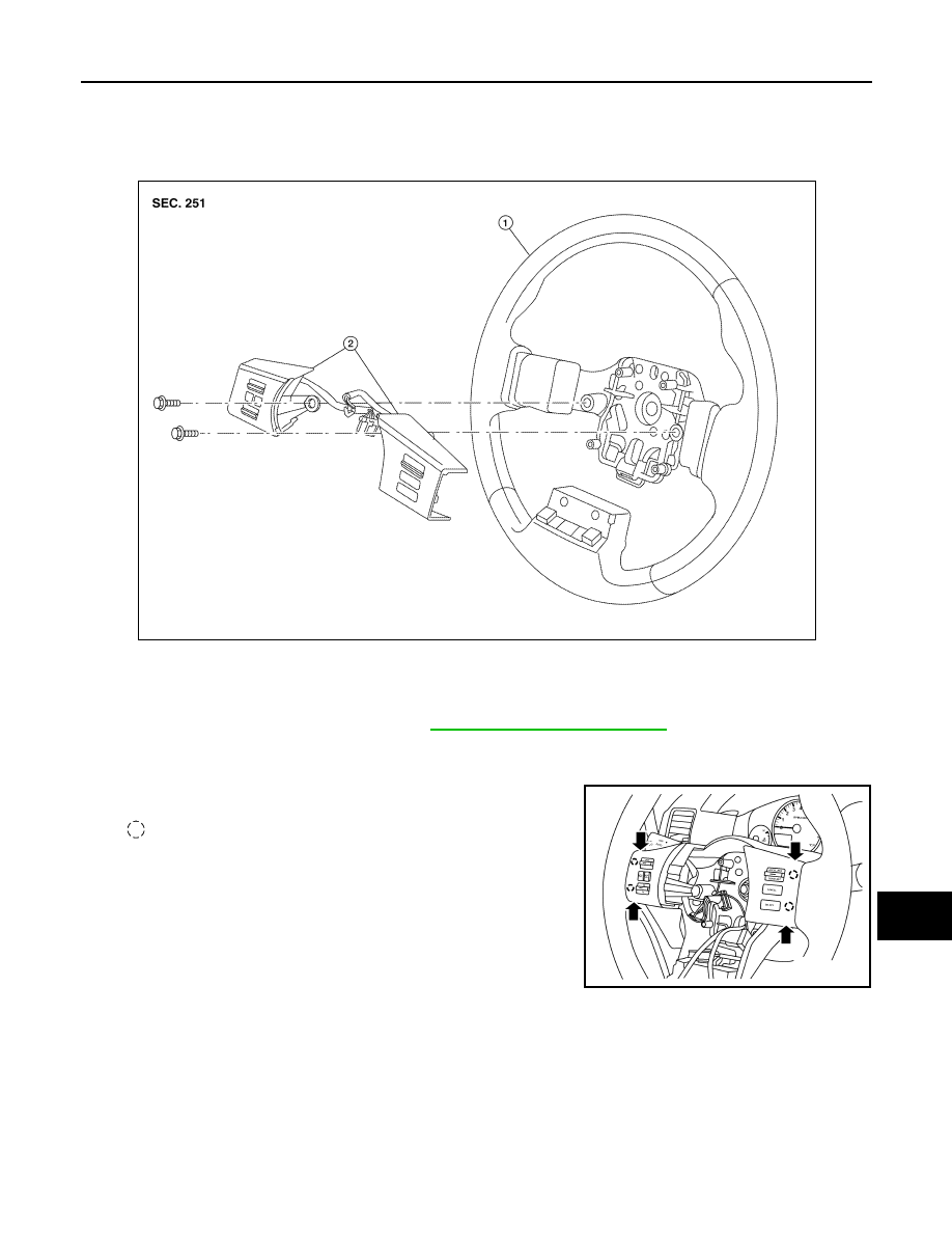
REMOVAL

1. Remove the driver air bag module. Refer to 

SR-5, "Removal and Installation"

.

2. Remove the steering wheel audio control switch assembly screws.
3. Disconnect the steering wheel audio control switches connector. 
4. Remove the steering wheel audio control switches by pulling on

steering wheel audio control switches to release the pawls.

:  Pawl

CAUTION:

Do not tilt steering wheel audio control switches during

removal or damage may occur to the pawls.

INSTALLATION

Installation is in the reverse order of removal.

1. Steering wheel

2.

Steering wheel audio control switches

ALNIA0357ZZ

ALNIA1214ZZ

2011 Pathfinder

AV-436

< REMOVAL AND INSTALLATION >

[BOSE AUDIO WITH NAVIGATION]

MICROPHONE

MICROPHONE

Removal and Installation

INFOID:0000000006246817

REMOVAL

1. Remove the front roof console finisher. Refer to 

INT-22, "Removal and Installation"

.

2. Detach the microphone (1) from the front console finisher tabs

(A).

3. Disconnect the microphone connector (B) and remove the

microphone (1).

INSTALLATION

Installation is in the reverse order of removal.

ALNIA0379ZZ

2011 Pathfinder

AV

REAR VIEW CAMERA

AV-437

< REMOVAL AND INSTALLATION >

[BOSE AUDIO WITH NAVIGATION]

C

D

E

F

G

H

I

J

K

L

M

B

A

O

P

REAR VIEW CAMERA

Removal and Installation

INFOID:0000000006246818

REMOVAL

1. Remove the license lamp finisher. Refer to 

EXT-23, "Removal and Installation"

.

2. Disconnect the rear view camera connector.
3. Detach the rear view camera harness clip.
4. Detach the rear view camera to release, then pull out to remove the rear view camera while feeding the

rear view camera harness and connector through the back door.

INSTALLATION

Installation is in the reverse order of removal.

1.

Rear view camera

A.

Rear view camera connector

B.

Rear view camera harness clip

ALNIA1182ZZ

2011 Pathfinder

BCS

BCS-1

ELECTRICAL & POWER CONTROL

C

D

E

F

G

H

I

J

K

L

B

SECTION 

BCS

A

O

P

N

CONTENTS

BODY CONTROL SYSTEM

BASIC INSPECTION  ....................................

3

INSPECTION AND ADJUSTMENT .....................

3

ADDITIONAL SERVICE WHEN REPLACING 
CONTROL UNIT  ........................................................
..

3

ADDITIONAL SERVICE WHEN REPLACING 
CONTROL UNIT : Description  ................................
..

3

ADDITIONAL SERVICE WHEN REPLACING 
CONTROL UNIT : Special Repair Requirement  .....
..

3

CONFIGURATION .......................................................

3

CONFIGURATION : Description  ...............................

3

CONFIGURATION : Special Repair Requirement ......

4

SYSTEM DESCRIPTION  ..............................

5

BODY CONTROL SYSTEM ................................

5

System Description  ...................................................

5

Component Parts Location ........................................

6

COMBINATION SWITCH READING SYSTEM 

.....

7

System Diagram ........................................................

7

System Description  ...................................................

7

Component Parts Location ......................................

10

SIGNAL BUFFER SYSTEM  ...............................

12

System Diagram ......................................................

12

System Description  .................................................

12

POWER CONSUMPTION CONTROL SYS-
TEM ....................................................................

13

System Diagram ......................................................

13

System Description  .................................................

13

Component Parts Location ......................................

15

DIAGNOSIS SYSTEM (BCM)  ............................

16

COMMON ITEM .........................................................

16

COMMON ITEM : CONSULT-III Function (BCM - 
COMMON ITEM) .....................................................

16

DOOR LOCK ..............................................................

17

DOOR LOCK : CONSULT-III Function (BCM - 
DOOR LOCK) ..........................................................

17

REAR DEFOGGER ....................................................

18

REAR DEFOGGER : CONSULT-III Function 
(BCM - REAR DEFOGGER)  ...................................

18

BUZZER .....................................................................

18

BUZZER : CONSULT-III Function (BCM - BUZZ-
ER) ..........................................................................

18

INT LAMP ...................................................................

18

INT LAMP : CONSULT-III Function (BCM - INT 
LAMP) ......................................................................

18

MULTI REMOTE ENT  ................................................

19

MULTI REMOTE ENT : CONSULT-III Function 
(BCM - MULTI REMOTE ENT) ................................

19

HEADLAMP ...............................................................

21

HEADLAMP : CONSULT-III Function (BCM - 
HEAD LAMP) ...........................................................

21

WIPER ........................................................................

22

WIPER : CONSULT-III Function (BCM - WIPER) ....

22

FLASHER ...................................................................

22

FLASHER : CONSULT-III Function (BCM - 
FLASHER) ...............................................................

22

AIR CONDITIONER  ...................................................

23

AIR CONDITIONER : CONSULT-III Function 
(BCM - AIR CONDITIONER) ...................................

23

INTELLIGENT KEY ....................................................

23

INTELLIGENT KEY : CONSULT-III Function 
(BCM - INTELLIGENT KEY) ....................................

23

COMB SW ..................................................................

23

COMB SW : CONSULT-III Function (BCM - 
COMB SW) ..............................................................

23

BCM ...........................................................................

24

2011 Pathfinder

BCS-2

BCM : CONSULT-III Function (BCM - BCM)  ..........

24

IMMU .........................................................................

24

IMMU : CONSULT-III Function (BCM - IMMU) .......

24

BATTERY SAVER  ....................................................

24

BATTERY SAVER : CONSULT-III Function (BCM 
- BATTERY SAVER)  .............................................
.

24

TRUNK ......................................................................

25

TRUNK : CONSULT-III Function (BCM - TRUNK) ...

25

THEFT ALM  ..............................................................

25

THEFT ALM : CONSULT-III Function (BCM - 
THEFT ALM)  .........................................................
.

25

RETAINED PWR  .......................................................

26

RETAINED PWR : CONSULT-III Function (BCM - 
RETAINED PWR)  ..................................................
.

26

SIGNAL BUFFER ......................................................

27

SIGNAL BUFFER : CONSULT-III Function (BCM 
- SIGNAL BUFFER) ...............................................
.

27

AIR PRESSURE MONITOR ......................................

27

AIR PRESSURE MONITOR : CONSULT-III Func-
tion (BCM - AIR PRESSURE MONITOR) ..............
.

27

PANIC ALARM ..........................................................

28

PANIC ALARM : CONSULT-III Function (BCM - 
PANIC ALARM)  .....................................................
.

28

DTC/CIRCUIT DIAGNOSIS .........................

29

U1000 CAN COMM CIRCUIT  ............................

29

Description ..............................................................

29

DTC Logic ...............................................................

29

Diagnosis Procedure  ..............................................

29

POWER SUPPLY AND GROUND CIRCUIT  .....

30

Diagnosis Procedure  ..............................................

30

COMBINATION SWITCH INPUT CIRCUIT  .......

32

Diagnosis Procedure  ..............................................

32

Special Repair Requirement ...................................

33

COMBINATION SWITCH OUTPUT CIRCUIT ...

34

Diagnosis Procedure ...............................................

34

Special Repair Requirement  ...................................

34

COMBINATION SWITCH  ..................................

35

Description ..............................................................

35

Diagnosis Procedure ...............................................

35

ECU DIAGNOSIS INFORMATION .............

37

BCM (BODY CONTROL MODULE) ..................

37

Reference Value  .....................................................

37

Terminal Layout  ......................................................

40

Physical Values .......................................................

40

Fail Safe .................................................................

45

DTC Inspection Priority Chart ...............................

45

DTC Index ..............................................................

46

WIRING DIAGRAM  ....................................

48

BCM (BODY CONTROL MODULE) ..................

48

Wiring Diagram  .......................................................

48

SYMPTOM DIAGNOSIS  ............................

52

COMBINATION SWITCH SYSTEM SYMP-
TOMS .................................................................

52

Symptom Table .......................................................

52

PRECAUTION ............................................

53

PRECAUTIONS  .................................................

53

Precaution for Supplemental Restraint System 
(SRS) "AIR BAG" and "SEAT BELT PRE-TEN-
SIONER" .................................................................

53

Precaution Necessary for Steering Wheel Rota-
tion After Battery Disconnect  ..................................

53

REMOVAL AND INSTALLATION ..............

55

BCM (BODY CONTROL MODULE) ..................

55

Removal and Installation .........................................

55

2011 Pathfinder

BCS

INSPECTION AND ADJUSTMENT

BCS-3

< BASIC INSPECTION >

C

D

E

F

G

H

I

J

K

L

B

A

O

P

N

BASIC INSPECTION

INSPECTION AND ADJUSTMENT

ADDITIONAL SERVICE WHEN REPLACING CONTROL UNIT
ADDITIONAL SERVICE WHEN REPLACING CONTROL UNIT : Description

INFOID:0000000006247430

When replacing BCM, save or print current vehicle specification with CONSULT-III configuration before

replacement.

Configuration has three functions as follows

• READ CONFIGURATION is the function to read (extract) vehicle configuration of current BCM.

• WRITE CONFIGURATION - Manual selection is the function to select and write vehicle configuration on

BCM manually.

• WRITE CONFIGURATION - Config file is the function to write vehicle configuration with the data extracted

from current BCM.

CAUTION:

• When replacing BCM, you must perform WRITE CONFIGURATION with CONSULT-III.

• Complete the procedure of WRITE CONFIGURATION in order.

• If you set incorrect WRITE CONFIGURATION, incidents will occur.

• Configuration is different for each vehicle model. Confirm configuration of each vehicle model.

ADDITIONAL SERVICE WHEN REPLACING CONTROL UNIT : Special Repair Re-
quirement

INFOID:0000000006247431

1.

 SAVING VEHICLE SPECIFICATION

Perform “READ CONFIGURATION” with CONSULT-III to save or print current vehicle specification.

>> GO TO 2

2.

 REPLACE BCM

Replace BCM. Refer to 

BCS-55, "Removal and Installation"

.

>> GO TO 3

3.

 WRITING VEHICLE SPECIFICATION

Perform “WRITE CONFIGURATION - Config file” or “WRITE CONFIGURATION - Manual selection” with

CONSULT-III to write vehicle specification. Refer to 

BCS-3, "ADDITIONAL SERVICE WHEN REPLACING

CONTROL UNIT : Special Repair Requirement"

.

>> GO TO 4

4.

 INITIALIZE BCM (NATS)

Perform BCM initialization. (NATS)

>> Work End.

CONFIGURATION
CONFIGURATION : Description

INFOID:0000000006247432

Vehicle specification needs to be written with CONSULT-III because it is not written after replacing BCM.

Configuration has three functions as follows

• READ CONFIGURATION is the function to read (extract) vehicle configuration of current BCM.

• WRITE CONFIGURATION - Manual selection is the function to select and write vehicle configuration on

BCM manually.

• WRITE CONFIGURATION - Config file is the function to write vehicle configuration with the data extracted

from current BCM.

CAUTION:

2011 Pathfinder

BCS-4

< BASIC INSPECTION >

INSPECTION AND ADJUSTMENT

• When replacing BCM, you must perform WRITE CONFIGURATION with CONSULT-III.

• Complete the procedure of WRITE CONFIGURATION in order.

• If you set incorrect WRITE CONFIGURATION, incidents will occur.

• Configuration is different for each vehicle model. Confirm configuration of each vehicle model.

CONFIGURATION : Special Repair Requirement

INFOID:0000000006247433

1.

 WRITING VEHICLE SPECIFICATION

Perform “WRITE CONFIGURATION” with CONSULT-III.

When writing saved data>>GO TO 2

When writing manually>>GO TO 3

2.

 PERFORM “WRITE CONFIGURATION - CONFIG FILE”

Perform “WRITE CONFIGURATION - Config file” with CONSULT-III.

>> Work End.

3.

 PERFORM “WRITE CONFIGURATION - MANUAL SELECTION”

For “WRITE CONFIGURATION - Manual selection”, using the following flow chart, identify the correct model

and configuration list.

Confirm and/or change setting value for each item according to the configuration list.

Depending on CONSULT-III software version being used, some or all of the write configuration items shown in

the following configuration lists may be displayed. If an item does not display on the CONSULT-III “WRITE

CONFIGURATION - Manual selection” screen, then it is an auto setting item and it cannot be manually set or

changed.

NOTE:

Confirm vehicle model. Refer to 

GI-20, "Model Variation"

.

>> Work End.

MANUAL SETTING ITEM

Items

Setting value

KEYLESS ENTRY

WITH

WITHOUT

I-KEY

WITH

WITHOUT

AUTO LIGHT

WITH

WITHOUT

DTRL

WITH

WITHOUT

THEFT ALARM

WITH

WITHOUT

ASSIST LAMP TYPE

MODE1

MODE2

AUTO DOOR UNLOCK TIMING

WITH I-KEY

WITHOUT I-KEY

2011 Pathfinder

BCS

BODY CONTROL SYSTEM

BCS-5

< SYSTEM DESCRIPTION >

C

D

E

F

G

H

I

J

K

L

B

A

O

P

N

SYSTEM DESCRIPTION

BODY CONTROL SYSTEM

System Description

INFOID:0000000006247434

OUTLINE

• BCM (Body Control Module) controls the various electrical components. It inputs the information required to

the control from CAN communication and the signal received from each switch and sensor. 

• BCM has combination switch reading function for reading the operation status of combination switches (light,

turn signal, wiper and washer) in addition to a function for controlling the operation of various electrical com-

ponents. It also has the signal transmission function as the passed point of signal and the power consump-

tion control function that reduces the power consumption with the ignition switch OFF.

• BCM is equipped with the diagnosis function that performs the diagnosis with CONSULT-III and various set-

tings.

BCM control function list

System

Refer to

Combination switch reading system

BCS-7, "System Diagram"

Signal buffer system

BCS-12, "System Diagram"

Power consumption control system

BCS-13, "System Diagram"

Auto light system

EXL-12, "System Diagram"

Turn signal and hazard warning lamp system

EXL-17, "System Diagram"

Headlamp system

EXL-7, "System Diagram"

Front fog lamp system (if equipped)

EXL-15, "System Diagram"

Daytime running light system (if equipped)

EXL-9, "System Diagram"

Interior room lamp control system

INL-6, "System Diagram"

Step lamp system

INL-6, "System Diagram"

Interior room lamp battery saver system

INL-6, "System Diagram"

Front wiper and washer system

WW-4, "System Diagram"

Rear wiper and washer system

WW-8, "System Diagram"

Warning chime system

WCS-4, "WARNING CHIME SYSTEM : System Diagram"

Door lock system

• WITH INTELLIGENT KEY SYSTEM: 

DLK-15, "DOOR LOCK AND UN-

LOCK SWITCH : System Diagram"

• WITHOUT INTELLIGENT KEY SYSTEM: 

DLK-214, "DOOR LOCK AND 

UNLOCK SWITCH : System Diagram"

(NATS) Nissan anti-theft system

• WITH INTELLIGENT KEY SYSTEM: 

SEC-15, "System Diagram"

• WITHOUT INTELLIGENT KEY SYSTEM: 

SEC-120, "System Diagram"

Vehicle security system

• WITH INTELLIGENT KEY SYSTEM: 

SEC-19, "System Diagram"

• WITHOUT INTELLIGENT KEY SYSTEM: 

SEC-123, "System Diagram"

Rear window defogger system

DEF-4, "System Diagram"

Remote keyless entry system

DLK-216, "REMOTE KEYLESS ENTRY : System Diagram"

Intelligent Key system (if equipped)

DLK-43, "CONSULT-III Function (INTELLIGENT KEY)"

Power window system

PWC-6, "System Diagram"

RAP (retained accessory power) system

BCS-26, "RETAINED PWR : CONSULT-III Function (BCM - RETAINED 
PWR)"

TPMS (tire pressure monitoring system)

WT-8, "System Diagram"

2011 Pathfinder


Content      ..     75      76      77      78     ..