Nissan Pathfinder (2010 year). Manual - part 650


  Index      Manuals     Nissan Pathfinder (2010 year) - Service and Repair Manual


Search            copyright infringement  


Content      ..     648      649      650      651     ..


Nissan Pathfinder (2010 year). Manual - part 650


WCS

WARNING CHIME SYSTEM

WCS-11

< FUNCTION DIAGNOSIS >

C

D

E

F

G

H

I

J

K

L

M

B

A

O

P

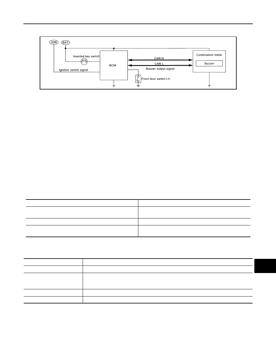
KEY WARNING CHIME (WITHOUT INTELLIGENT KEY) : System Diagram

INFOID:0000000005256303

KEY WARNING CHIME (WITHOUT INTELLIGENT KEY) : System Description

INFOID:0000000005256304

With the key inserted into the key switch, and the ignition switch in the OFF or ACC position, when driver's

door is opened, the warning chime will sound.

• BCM detects key inserted into the ignition switch, and sends key warning signal to combination meter with

CAN communication line. 

• When combination meter receives key warning signal, it sounds warning chime.

KEY WARNING CHIME (WITHOUT INTELLIGENT KEY) : System Description

INFOID:0000000005256305

COMBINATION METER

• The buzzer for warning chime system is installed in the combination meter.

• The buzzer sounds when the combination meter receives a buzzer output signal from each unit.

BCM

BCM receives signals from various units and transmits a buzzer output signal to the combination meter with

CAN communication line if it judges that the warning buzzer should be activated.

BCM warning function list

KEY WARNING CHIME (WITHOUT INTELLIGENT KEY) : Component Description

INFOID:0000000005256306

WKIA5463E

Warning functions

Signal name

Light reminder warning chime

• Lighting switch position signal
• Door switch signal

Seat belt warning chime

Seat belt buckle switch signal

Key warning chime

• Key switch signal
• Door switch signal

Unit

Description

Combination meter

Receives key warning signal from BCM via CAN communication line and sounds the buzzer.

BCM

Judges the key warning condition from the door switch signal received from the front door switch 
LH, and the key switch signal received from the key switch. It then transmits a buzzer output signal 
to the combination meter via CAN communication line if necessary.

Front door switch LH

Transmits door switch signal to BCM.

Key switch

Transmits key switch signal to BCM.

2010 Pathfinder

WCS-12

< FUNCTION DIAGNOSIS >

DIAGNOSIS SYSTEM (METER)

DIAGNOSIS SYSTEM (METER)

Diagnosis Description

INFOID:0000000005511852

SELF-DIAGNOSIS MODE

The following items can be checked during Combination Meter Self-Diagnosis Mode.

• Gauge sweep and present gauge values.

• Illuminates all odometer/trip meters and A/T indicator segments.

• Illuminates all micro controlled lamps/LEDs regardless of switch position.

• Displays estimated present battery voltage.

• Displays seat belt buckle switch LH status.

OPERATION PROCEDURE

NOTE:

• Once entered, combination meter self-diagnosis mode will function with the ignition switch in ON or START.

Combination meter self-diagnosis mode will exit upon turning the ignition switch to OFF or ACC. 

• If the diagnosis function is activated with trip A displayed, the mileage on trip A is reset to 0000.0. (Trip B

operates the same way.)

To initiate combination meter self-diagnosis mode, refer to the following procedure.

1. Turn the ignition switch ON, while pressing the odometer/trip meter switch for 5 - 8 seconds. When the

diagnosis function is activated, the odometer/trip meter will display tESt.

NOTE:

Check combination meter power supply and ground circuit when self-diagnosis mode of combination meter

does not start. Refer to 

MWI-29, "COMBINATION METER : Diagnosis Procedure"

. Replace combination

meter if normal. Refer to 

MWI-96, "Removal and Installation"

.

COMBINATION METER SELF-DIAGNOSIS MODE FUNCTIONS

To interpret combination meter self-diagnosis mode functions, refer to the following table.

Event

Odometer Display

Description of Test/Data

Notes:

Odometer/trip meter A/B 
switch held from 5 to 8 
seconds (or until re-
leased)

tESt

Initiating self-diagnosis mode

Switch released

GAGE

Performs sweep of all 
gauges, then displays 
present gauge values.

Gauges sweep within 10 seconds

Switch pressed

(All segments illuminated)

Lights all LCD segments. 
Compare with picture.

USA

Canada

Switch pressed

bulb

Illuminates all micro-con-
trolled lamps/LEDs.

Part may not be configured for all 
lamps (functions) that turn on dur-
ing test. This is normal.

Switch pressed

r XXXX, FAIL

Return to normal opera-
tion of all lamps/LEDs and 
displays “r XXXX”.

If a malfunction exists, “FAIL” will 
flash.

AWNIA0219ZZ

AWNIA0220ZZ

2010 Pathfinder

WCS

DIAGNOSIS SYSTEM (METER)

WCS-13

< FUNCTION DIAGNOSIS >

C

D

E

F

G

H

I

J

K

L

M

B

A

O

P

CONSULT-III Function (METER/M&A)

INFOID:0000000005484857

CONSULT-III can display each diagnostic item using the diagnostic test modes shown following.

Switch pressed

nrXXXX

Displays Hex ROM rev as 
stored in NVM.

Switch pressed

EE XX, FAIL

Displays “EE XX”.

If a malfunction exists, “FAIL” will 
flash.

Switch pressed

dtXXXX

Hex coding of final manu-
facturing test date.

Switch pressed
(3 times)

Sc1 XX through Epr XX

Displays 8 bit software 
configuration value in Hex 
format

Switch pressed

1nF XX

Displays 8-bit market info 
value in Hex format.

$31 = USA
$2A = Canada

Switch pressed
(3 times)

cYL XX through tF

N/A

Switch pressed

ot1 XX

Displays oil pressure tell-
tale “” in Hex format.

Switch pressed

ot0 XX

Displays oil pressure tell-
tale “” in Hex format.

Switch pressed

XXXXX

“Corrected” speed value 
in hundredths of MPH. 
Gauge indication may be 
slightly higher. This is nor-
mal.

Will display “-----” if message is not 
received. Will display “99999” if 
data received is invalid.

Switch pressed

XXXXX

“Corrected” speed value 
in hundredths of KPH. 
Gauge indication may be 
slightly different. This is 
normal.

Will display “-----” if message is not 
received. Will display “99999” if 
data received is invalid.

Switch pressed

t XXXX

Tachometer value in 
RPM. Gauge indication 
may be higher at higher 
RPM. This is normal.

Will display “-----” if message is not 
received.

Switch pressed

F1XXXX

Present fuel level A/D in-
put. This input represents 
fuel sender input.

000-009 = Short circuit
010-254 = Normal range
255 = Open circuit

Switch pressed

XXXC

Last temperature gauge 
input value in degrees C. 
Temperature gauge indi-
cates present tempera-
ture per indication 
standard.

Will display “---”C if message is not 
received.
Will display “999” if data received 
is invalid.
High = 130 deg C
Normal = 70 - 105 deg C
Low = less than 50 deg C

Switch pressed

BAtXX.X

Estimated present battery 
voltage.

Switch pressed

rES -X

Seat belt buckle switch LH 
status.

1= Buckled
0 = Unbuckled

Switch pressed
(30 times)

PA -XX through PA1-XX

N/A

Switch pressed

GAGE

Return to beginning of self-diagno-
sis cycle.

Event

Odometer Display

Description of Test/Data

Notes:

2010 Pathfinder

WCS-14

< FUNCTION DIAGNOSIS >

DIAGNOSIS SYSTEM (METER)

SELF-DIAG RESULTS

Display Item List

Refer to 

WCS-51, "DTC Index"

.

DATA MONITOR

Display Item List

X: Applicable

METER/M&A diagnosis mode

Description

SELF-DIAG RESULTS

Displays combination meter self-diagnosis results.

DATA MONITOR

Displays combination meter input/output data in real time.

CAN DIAG SUPPORT MNTR

The result of transmit/receive diagnosis of CAN communication can be read.

Display item [Unit]

MAIN

SIGNALS

SELECTION 

FROM MENU

Description

SPEED METER [km/h] or [mph]

X

X

Displays the value of vehicle speed signal.

SPEED OUTPUT [km/h] or [mph]

X

X

Displays the value of vehicle speed signal, which is transmitted to 
each unit with CAN communication.

TACHO METER [rpm]

X

X

Displays the value of engine speed signal, which is input from ECM.

FUEL METER [lit.]

X

X

Displays the value, which processes a resistance signal from fuel 
gauge.

W TEMP METER [

°

C] or [

°

F]

X

X

Displays the value of engine coolant temperature signal, which is in-
put from ECM. 

ABS W/L [ON/OFF]

X

Displays [ON/OFF] condition of ABS warning lamp.

VDC/TCS IND [ON/OFF]

X

Displays [ON/OFF] condition of VDC OFF indicator lamp.

SLIP IND [ON/OFF]

X

Displays [ON/OFF] condition of SLIP indicator lamp.

BRAKE W/L [ON/OFF]

X

Displays [ON/OFF] condition of brake warning lamp.*

DOOR W/L [ON/OFF]

X

Displays [ON/OFF] condition of door ajar warning lamp.

HI-BEAM IND [ON/OFF]

X

Displays [ON/OFF] condition of high beam indicator.

TURN IND [ON/OFF]

X

Displays [ON/OFF] condition of turn indicator.

OIL W/L [ON/OFF]

X

Displays [ON/OFF] condition of oil pressure warning lamp.

C-ENG W/L [ON/OFF] 

X

Displays [ON/OFF] condition of malfunction indicator lamp.

CRUISE IND [ON/OFF]

X

Displays [ON/OFF] condition of CRUISE indicator.

SET IND [ON/OFF]

X

Displays [ON/OFF] condition of SET indicator.

O/D OFF W/L [ON/OFF]

X

Displays [ON/OFF] condition of AT CHECK (with manual mode) or 
O/D OFF (without manual mode) warning lamp.

FUEL W/L [ON/OFF]

X

X

Displays [ON/OFF] condition of low-fuel warning lamp.

AIR PRES W/L [ON/OFF]

X

Displays [ON/OFF] condition of tire pressure warning lamp.

KEY G/Y W/L [ON/OFF]

X

Displays [ON/OFF] condition of key green warning lamp.

KEY R W/L [ON/OFF]

X

Displays [ON/OFF] condition of key red warning lamp.

KEY KNOB W/L [ON/OFF]

X

Displays [ON/OFF] condition of key knob warning lamp.

M RANGE SW [ON/OFF]

X

X

Displays [ON/OFF] condition of manual mode range switch.

NM RANGE SW [ON/OFF]

X

X

Displays [ON/OFF] condition of except for manual mode range 
switch.

AT SFT UP SW [ON/OFF]

X

X

Displays [ON/OFF] condition of A/T shift-up switch.

AT SFT DWN SW [ON/OFF]

X

X

Displays [ON/OFF] condition of A/T shift-down switch.

DISTANCE [km] or [mile]

X

X

Displays the value, which is calculated by vehicle speed signal, fuel 
gauge and fuel consumption from ECM.

BUZZER [ON/OFF]

X

X

Displays [ON/OFF] condition of buzzer.

BRAKE SW [ON/OFF]

X

Indicates [ON/OFF] condition of parking brake switch.

2010 Pathfinder

WCS

DIAGNOSIS SYSTEM (METER)

WCS-15

< FUNCTION DIAGNOSIS >

C

D

E

F

G

H

I

J

K

L

M

B

A

O

P

NOTE:

Some items are not available due to vehicle specification.
*: The monitor will indicate “OFF” even though the brake warning lamp is on if either of the following conditions exist. 
• The parking brake is engaged
• The brake fluid level is low

AT-M IND [ON/OFF]

X

X

Indicates [ON/OFF] condition of A/T manual mode indicator.

AT-M GEAR [1, 2, 3, 4]

X

X

Indicates [1, 2, 3, 4] condition of A/T manual mode gear position.

P RANGE IND [ON/OFF] 

X

X

Indicates [ON/OFF] condition of A/T shift P range indicator.

R RANGE IND [ON/OFF]

X

X

Indicates [ON/OFF] condition of A/T shift R range indicator.

N RANGE IND [ON/OFF]

X

X

Indicates [ON/OFF] condition of A/T shift N range indicator.

D RANGE IND [ON/OFF]

X

X

Indicates [ON/OFF] condition of A/T shift D range indicator.

4 RANGE IND [ON/OFF]

X

X

Indicates [ON/OFF] condition of A/T shift 4 range indicator.

3 RANGE IND [ON/OFF]

X

X

Indicates [ON/OFF] condition of A/T shift 3 range indicator.

2 RANGE IND [ON/OFF]

X

X

Indicates [ON/OFF] condition of A/T shift 2 range indicator.

1 RANGE IND [ON/OFF]

X

X

Indicates [ON/OFF] condition of A/T shift 1range indicator.

4WD LOCK SW [ON/OFF]

X

Indicates [ON/OFF] condition of 4WD lock switch.

4WD LOCK IND [ON/OFF]

X

Indicates [ON/OFF] condition of 4WD lock indicator.

SEAT BELT W/L [ON/OFF]

X

Indicates [ON/OFF] condition of seat belt warning lamp.

O/D OFF SWITCH [ON/OFF]

X

Indicates [ON/OFF] condition of O/D OFF switch.

Display item [Unit]

MAIN

SIGNALS

SELECTION 

FROM MENU

Description

2010 Pathfinder

WCS-16

< FUNCTION DIAGNOSIS >

DIAGNOSIS SYSTEM (BCM)

DIAGNOSIS SYSTEM (BCM)

BUZZER
BUZZER : CONSULT-III Function (BCM - BUZZER)

INFOID:0000000005484858

DATA MONITOR

ACTIVE TEST

Monitor Item

[Unit]

Description

DOOR SW -DR [ON/OFF]

Front door switch (driver side) status judged by BCM

IGN ON SW [ON/OFF]

Ignition switch (ON) status judged by ignition power supply input

KEY ON SW [ON/OFF]

Key switch status

LIGHT SW 1ST [ON/OFF]

Lighting switch status judged by the lighting switch signal read with combination switch reading func-
tion

BUCKLE SW [ON/OFF]

Seat belt buckle switch status

Test Item

Description

SEAT BELT WARN TEST

The seat belt warning operation can be checked by operating the relevant function (On/Off).

LIGHT WARN ALM

The light reminder warning operation can be checked by operating the relevant function (On/Off).

IGN KEY WARN ALM

The key reminder warning operation can be checked by operating the relevant function (On/Off).

2010 Pathfinder

WCS

POWER SUPPLY AND GROUND CIRCUIT

WCS-17

< COMPONENT DIAGNOSIS >

C

D

E

F

G

H

I

J

K

L

M

B

A

O

P

COMPONENT DIAGNOSIS

POWER SUPPLY AND GROUND CIRCUIT

COMBINATION METER
COMBINATION METER : Diagnosis Procedure

INFOID:0000000005484859

Regarding Wiring Diagram information, refer to 

MWI-42, "Wiring Diagram"

.

1.

CHECK FUSES

Check for blown combination meter fuses.

Is the inspection result normal?

YES

>> GO TO 2

NO

>> If fuse is blown, be sure to eliminate cause of malfunction before installing new fuse.

2.

POWER SUPPLY CIRCUIT CHECK

1. Disconnect combination meter connector M24.

2. Check voltage between combination meter harness connector

M24 terminals 3, 16 and ground.

Is the inspection result normal?

YES

>> GO TO 3

NO

>> Check harness for open between combination meter and fuse.

3.

GROUND CIRCUIT CHECK

1. Turn ignition switch OFF.

2. Check continuity between combination meter harness connector

M24 terminals 13, 23 and ground.

Is the inspection result normal?

YES

>> Inspection End.

NO

>> Check ground harness.

BCM (BODY CONTROL MODULE)

Unit

Power source

Fuse No.

Combination meter

Battery 19

Ignition switch ON or START 

14

Terminals

Ignition switch position

(+)

(–)

OFF

ACC

ON

Connector

Terminal

M24

3

Ground

Battery 
voltage

Battery 
voltage

Battery

 voltage

16

0V

0V

Battery
voltage

WKIA3279E

Terminals

Continuity

(+)

(–)

Connector

Terminal

M24

13

Ground

Yes

23

WKIA3280E

2010 Pathfinder

WCS-18

< COMPONENT DIAGNOSIS >

POWER SUPPLY AND GROUND CIRCUIT

BCM (BODY CONTROL MODULE) : Diagnosis Procedure

INFOID:0000000005484860

Regarding Wiring Diagram information, refer to 

BCS-50, "Wiring Diagram"

.

1.

 CHECK FUSES AND FUSIBLE LINK

Check that the following fuses and fusible link are not blown.

Is the fuse blown?

YES

>> Replace the blown fuse or fusible link after repairing the affected circuit.

NO

>> GO TO 2

2.

 CHECK POWER SUPPLY CIRCUIT

1. Turn ignition switch OFF.

2. Disconnect BCM.

3. Check voltage between BCM harness connector and ground.

Is the measurement value normal?

YES

>> GO TO 3

NO

>> Repair or replace harness.

3.

 CHECK GROUND CIRCUIT

Check continuity between BCM harness connector and ground.

Does continuity exist?

YES

>> Inspection End.

NO

>> Repair or replace harness.

Terminal No.

Signal name

Fuses and fusible link No.

57

Battery power supply

18 (10A)

70

G (50A)

11

Ignition ACC or ON

4 (10A)

38

Ignition ON or START

1 (10A)

Connector

Terminals 

Power

source

Condition

Voltage (V) (Ap-

prox.)

(+)

(-)

M18

11

Ground

ACC 

power 

supply

Ignition 

switch 

ACC or 

ON

Battery voltage

38

Ground

Ignition 

power 

supply

Ignition 

switch ON 

or START

Battery voltage

M20

57

Ground

Battery 

power 

supply

Ignition 

switch 

OFF

Battery voltage

70

Ground

Battery 

power 

supply

Ignition 

switch 

OFF

Battery voltage

LIIA2415E

BCM

Ground

Continuity

Connector

Terminal

M20

67

Yes

LIIA0915E

2010 Pathfinder


Content      ..     648      649      650      651     ..