Nissan Pathfinder (2010 year). Manual - part 535
DOOR SWITCH
PWC-33
< COMPONENT DIAGNOSIS >
C
D
E
F
G
H
I
J
L
M
A
B
PWC
N
O
P
DOOR SWITCH
Description
INFOID:0000000005256030
Detects door open/close condition and transmits the signal to BCM.
Component Function Check
INFOID:0000000005256031
1.
CHECK FRONT DOOR SWITCH INPUT SIGNAL
Check (“DOOR SW-DR” and “DOOR SW-AS”) in “DATA MONITOR” mode with CONSULT-III. Refer to
27, "RETAINED PWR : CONSULT-III Function (BCM - RETAINED PWR)"
Is the inspection result normal?
YES
>> Front door switch circuit is OK.
NO
>> Refer to
.
Diagnosis Procedure
INFOID:0000000005256032
Regarding Wiring Diagram information, refer to
.
1.
CHECK FRONT DOOR SWITCH
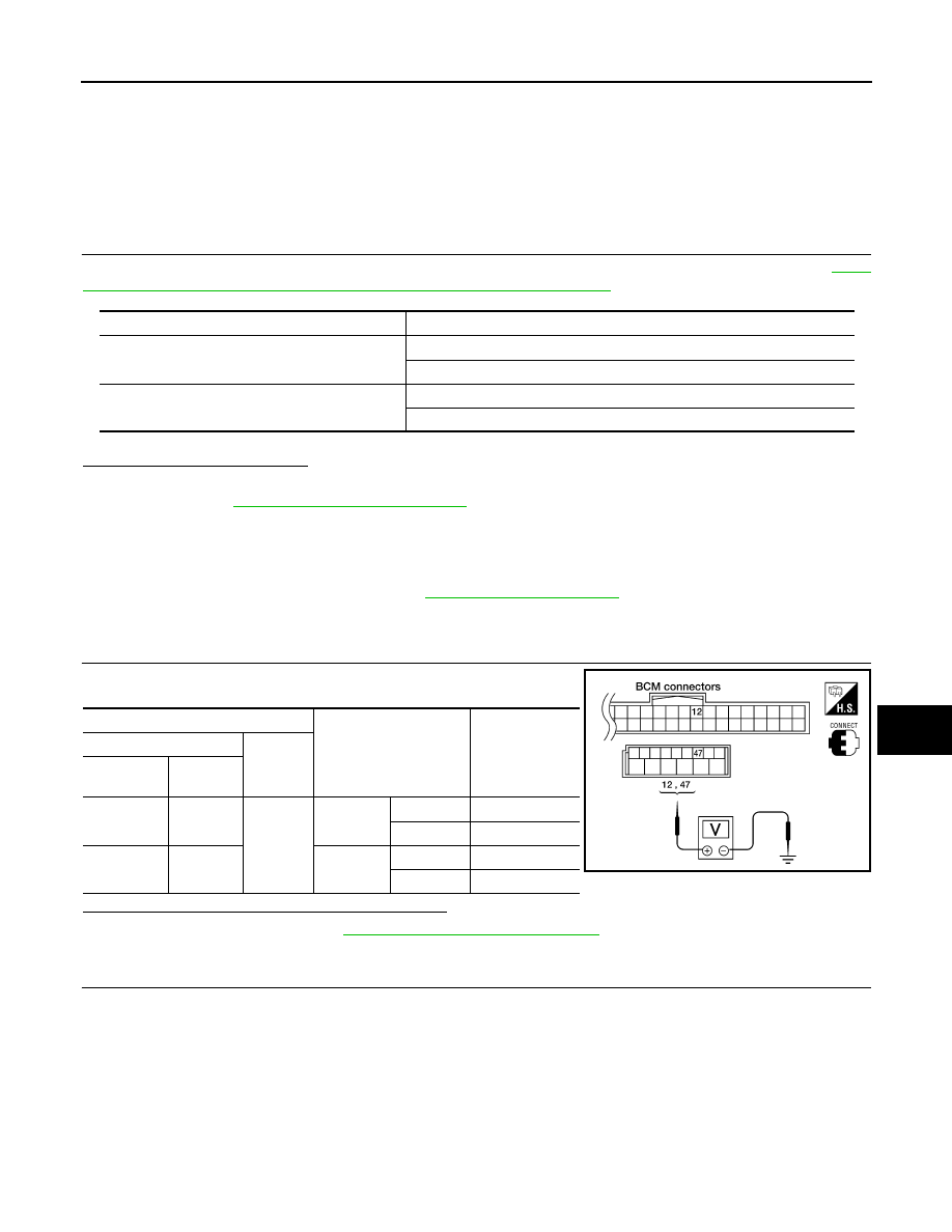
Check voltage between BCM connector and ground.
Is the measurement value within the specification?
YES
>> Replace BCM. Refer to
BCS-59, "Removal and Installation"
NO
>> GO TO 2
2.
CHECK HARNESS CONTINUITY
Monitor item
Condition
DOOR SW-DR
OPEN
: ON
CLOSE
: OFF
DOOR SW-AS
OPEN
: ON
CLOSE
: OFF
Terminals
Door condition
Voltage (V)
(Approx.)
(+)
(–)
BCM
connector
Terminal
M18
12
Ground
Front door
RH
OPEN
0
CLOSE
Battery voltage
M19
47
Front door
LH
OPEN
0
CLOSE
Battery voltage
LIIA0946E
2010 Pathfinder