Nissan Pathfinder (2010 year). Manual - part 397


  Index      Manuals     Nissan Pathfinder (2010 year) - Service and Repair Manual


Search            copyright infringement  


Content      ..     395      396      397      398     ..


Nissan Pathfinder (2010 year). Manual - part 397


EXL-42

< COMPONENT DIAGNOSIS >

FRONT FOG LAMP CIRCUIT

FRONT FOG LAMP CIRCUIT

Description

INFOID:0000000005259746

The IPDM E/R (intelligent power distribution module engine room) controls the front fog lamp relay based on

inputs from the BCM via the CAN communication lines. When the front fog lamp relay is energized, power

flows from the front fog lamp relay in the IPDM E/R to the front fog lamps. 

Component Function Check

INFOID:0000000005259747

1.

CHECK FRONT FOG LAMP OPERATION

WITHOUT CONSULT-III

1. Activate IPDM E/R auto active test. Refer to 

PCS-12, "Diagnosis Description"

.

2. Check that the front fog lamp is turned ON.

CONSULT-III

1. Select "EXTERNAL LAMPS" of IPDM E/R active test item.

2. With operating the test items, Check that the front fog lamp is turned ON.

Is the front fog lamp turned ON?

YES

>> Front fog lamp circuit is normal.

NO

>> Refer to 

EXL-42, "Diagnosis Procedure"

Diagnosis Procedure

INFOID:0000000005259748

Regarding Wiring Diagram information, refer to 

EXL-73, "Wiring Diagram"

.

1.

CHECK FRONT FOG LAMP FUSE

1. Turn the ignition switch OFF.

2. Check that the following fuses are not open.

Is the fuse open?

YES

>> Repair the harness and replace the fuse.

NO

>> GO TO 2

2.

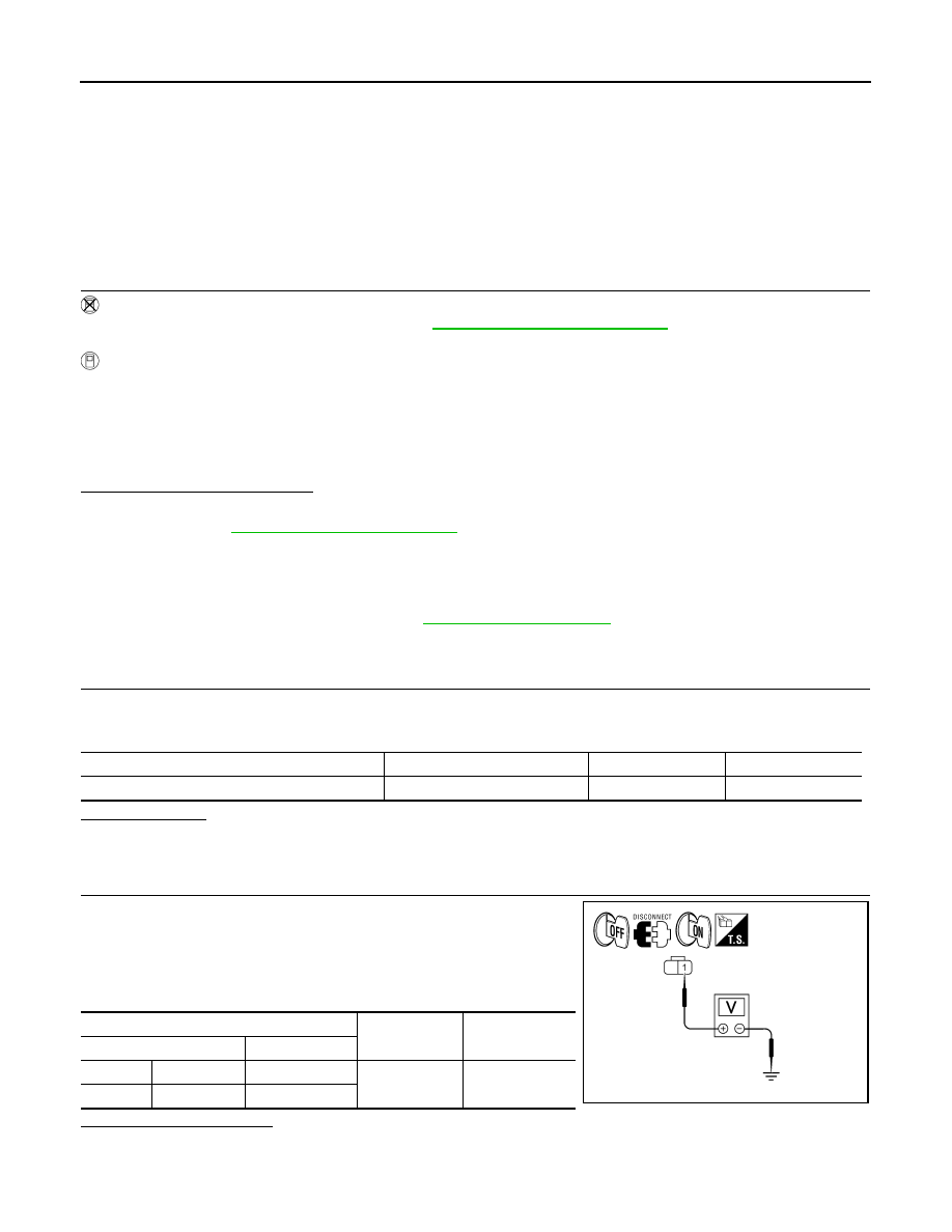
CHECK FRONT FOG LAMP OUTPUT VOLTAGE

1. Turn the ignition switch OFF.

2. Disconnect the front fog lamp connector.

3. Turn the ignition switch ON.

4. Turn the front fog lamps ON.

5. Check the voltage between the fog lamp connector and ground.

Is battery voltage present?

YES

>> GO TO 4

NO

>> GO TO 3

Fog

: Front fog lamp ON

Off

: Front fog lamp OFF

Unit

Location

Fuse No.

Capacity

Front fog lamp 

IPDM E/R

56

20A

(+)

(

)

Voltage

Connector

Terminal

LH

E101

1

Ground

Battery voltage

RH

E102

1

ALLIA0627GB

2010 Pathfinder

FRONT FOG LAMP CIRCUIT

EXL-43

< COMPONENT DIAGNOSIS >

C

D

E

F

G

H

I

J

K

M

A

B

EXL

N

O

P

3.

CHECK FRONT FOG LAMP OPEN CIRCUIT

1. Turn the ignition switch OFF.

2. Disconnect IPDM E/R connector.

3. Check continuity between the IPDM E/R harness connector (A)

and the front fog lamp harness connector (B).

Does continuity exist?

YES

>> GO TO 4 

NO

>> Repair the harnesses or connectors.

4.

CHECK FRONT FOG LAMP GROUND CIRCUIT

1. Disconnect the front fog lamp connector.

2. Check continuity between the front fog lamp harness connector

terminal and ground.

Does continuity exist?

YES

>> Inspect the fog lamp bulb.

NO

>> Repair the harness.

A

B

Continuity

Connector

Terminal

Connector

Terminal

LH

E123

50

E101

1

Yes

RH

51

E102

1

ALLIA0628GB

Connector

Terminal

Continuity

LH

E101

2

Ground

Yes

RH

E102

2

ALLIA0629GB

2010 Pathfinder

EXL-44

< COMPONENT DIAGNOSIS >

PARKING LAMP CIRCUIT

PARKING LAMP CIRCUIT

Description

INFOID:0000000005259749

The IPDM E/R (intelligent power distribution module engine room) controls the tail lamp relay based on inputs

from the BCM via the CAN communication lines. When the tail lamp relay is energized, power flows through

fuse 37, located in the IPDM E/R. Power then flows to the front and rear combination lamps.

Component Function Check

INFOID:0000000005259750

1.

CHECK PARKING LAMP OPERATION

WITHOUT CONSULT-III

1. Activate IPDM E/R auto active test. Refer to 

PCS-12, "Diagnosis Description"

.

2. Check that the parking lamp is turned ON.

CONSULT-III 

1. Select "EXTERNAL LAMPS" of IPDM E/R active test item.

2. With operating the test items, check that the parking lamp is turned ON.

Is the parking lamp turned ON?

YES

>> Parking lamp circuit is normal.

NO

>> Refer to 

EXL-44, "Diagnosis Procedure"

.

Diagnosis Procedure

INFOID:0000000005259751

Regarding Wiring Diagram information, refer to 

EXL-83, "Wiring Diagram"

.

1.

CHECK PARKING LAMP FUSES

1. Turn the ignition switch OFF.

2. Check that the following fuses are not open.

Is the fuse open?

YES

>> Repair the harness and replace the fuse.

NO

>> GO TO 2

2.

CHECK TAIL LAMP RELAY OUTPUT (VOLTAGE)

1. Turn the ignition switch OFF.

2. Disconnect the front combination lamp connectors, front side marker lamp connectors, rear combination

lamp connectors and license plate lamp connectors.

3. Turn the ignition switch ON.

4. Turn the parking lamps ON.

TAIL

: Parking lamp ON

Off

: Parking lamp OFF

Unit

Location

Fuse No.

Capacity

Parking lamps 

IPDM E/R

36

10A

37

10A

2010 Pathfinder

PARKING LAMP CIRCUIT

EXL-45

< COMPONENT DIAGNOSIS >

C

D

E

F

G

H

I

J

K

M

A

B

EXL

N

O

P

5. With the parking lamps ON, check voltage between the front

combination lamp connectors and ground.

6. With the parking lamps ON, check voltage between the front

side marker lamp connectors and ground.

7. With the parking lamps ON, check voltage between the rear

combination lamp connectors and ground.

8. With the parking lamps ON, check voltage between the license

plate lamp connector and ground

Are voltage readings as specified?

YES

>> GO TO 4

NO

>> GO TO 3

3.

CHECK PARKING, LICENSE PLATE AND TAIL LAMP CIRCUIT (OPEN)

(+)

(

)

Voltage

Connector

Terminal

LH

E27

2

Ground

Battery voltage

RH

E111

AWLIA1671ZZ

(+)

(

)

Voltage

Connector

Terminal

LH

E17

1

Ground

Battery voltage

RH

E108

AWLIA1672ZZ

(+)

(

)

Voltage

Connector

Terminal

LH

B35

1

Ground

Battery voltage

RH

B105

ALLIA0632GB

(+)

(

)

Voltage

Connector

Terminal

LH

D506

1

Ground

Battery voltage

RH

D507

ALLIA0633GB

2010 Pathfinder

EXL-46

< COMPONENT DIAGNOSIS >

PARKING LAMP CIRCUIT

1. Turn the ignition switch OFF.

2. Disconnect IPDM E/R connector.

3. Check continuity between the IPDM E/R harness connector

(A)(B) and the front parking lamp harness connector (C).

4. Check continuity between the IPDM E/R harness connector

(A)(B) and the front side marker lamp harness connector (C).

5. Check continuity between the IPDM E/R harness connector (A)

and the rear combination lamp harness connector (B).

Connector

Terminal

Connector

Terminal

Continuity

LH

A: E121

28

C: E27

2

Yes

RH

B: E123

49

C: E111

AWLIA1673ZZ

Connector

Terminal

Connector

Terminal

Continuity

LH

A: E121

28

C: E17

1

Yes

RH

B: E123

49

C: E108

AWLIA1674ZZ

A

B

Continuity

Connector

Terminal

Connector

Terminal

LH

E124

57

B35

1

Yes

RH

B105

ALLIA0637GB

2010 Pathfinder

PARKING LAMP CIRCUIT

EXL-47

< COMPONENT DIAGNOSIS >

C

D

E

F

G

H

I

J

K

M

A

B

EXL

N

O

P

6. Check continuity between the IPDM E/R harness connector (A)

and license plate lamp connector (B). 

Are continuity results as specified?

YES

>> GO TO 4

NO

>> Repair the harnesses or connectors.

4.

CHECK PARKING, LICENSE AND TAIL LAMP GROUND CIRCUITS

1. Check continuity between the front parking lamp harness con-

nectors and ground.

2. Check continuity between the front side marker lamp harness

connectors and ground.

3. Check continuity between the rear combination lamp harness

connectors and ground.

A

B

Continuity

Connector

Terminal

Connector

Terminal

E124

57

D506

1

Yes

D507

ALLIA0638GB

Connector

Terminal

Continuity

LH

E27

1

Ground

Yes

RH

E111

AWLIA1676ZZ

Connector

Terminal

Continuity

LH

E17

2

Ground

Yes

RH

E108

AWLIA1677ZZ

Connector

Terminal

Continuity

LH

B35

5

Ground

Yes

RH

B105

ALLIA0641GB

2010 Pathfinder

EXL-48

< COMPONENT DIAGNOSIS >

PARKING LAMP CIRCUIT

4. Check continuity between the license plate lamp harness con-

nectors and ground.

Are continuity results as specified?

YES

>> Inspect the parking lamp bulb.

NO

>> Repair the harness.

Connector

Terminal

Continuity

D506

2

Ground

Yes

D507

ALLIA0642GB

2010 Pathfinder

TURN SIGNAL LAMP CIRCUIT

EXL-49

< COMPONENT DIAGNOSIS >

C

D

E

F

G

H

I

J

K

M

A

B

EXL

N

O

P

TURN SIGNAL LAMP CIRCUIT

Description

INFOID:0000000005259752

The BCM monitors inputs from the combination switch to determine when to activate the turn signals. The

BCM outputs voltage direction to the left and right turn signals during turn signal operation or both during haz-

ard warning operation. The BCM sends a turn signal indicator request to the combination meter via the CAN

communication lines. 

The BCM performs the fast flasher operation (fail-safe) if any bulb or harness of the turn signal lamp circuit is

open.

NOTE:

Turn signal lamp blinks at normal speed when using the hazard warning lamp.

Component Function Check

INFOID:0000000005259753

1.

CHECK TURN SIGNAL LAMP

CONSULT-III

1. Select "FLASHER" of BCM (FLASHER) active test item.

2. With operating the test items, check that the turn signal lamp blinks.

Does the turn signal lamp blink?

YES

>> Turn signal lamp circuit is normal.

NO

>> Refer to 

EXL-49, "Diagnosis Procedure"

.

Diagnosis Procedure

INFOID:0000000005259754

Regarding Wiring Diagram information, refer to 

EXL-77, "Wiring Diagram"

.

1.

CHECK TURN SIGNAL LAMP BULB

Check the applicable lamp bulb to be sure the proper bulb standard is in use and the bulb is not open.
Is the bulb OK?

YES

>> GO TO 2

NO

>> Replace the bulb.

2.

CHECK TURN SIGNAL LAMP OUTPUT VOLTAGE

1. Turn the ignition switch OFF.

2. Disconnect the front combination lamp connectors and the rear

combination lamp connector.

3. Turn the ignition switch ON.

4. With turn signal switch operating, check the voltage between the

BCM harness connector M20 and ground.

LH

: Turn signal lamp LH blinking 

RH

: Turn signal lamp RH blinking 

Off

: The turn signal lamp OFF

(+)

(

)

Voltage

Connector

Terminal

ALLIA0402ZZ

2010 Pathfinder


Content      ..     395      396      397      398     ..