Nissan Pathfinder (2010 year). Manual - part 376
EM-136
< SERVICE DATA AND SPECIFICATIONS (SDS)
[VQ40DE]
SERVICE DATA AND SPECIFICATIONS (SDS)
1
: Always check with the Parts Department for the latest parts information
2
: Total indicator reading
MAIN BEARING
Main journal diameter. “Dm” grade
Standard
Grade
1
Dimension
Grade No. A
Grade No. B
Grade No. C
Grade No. D
Grade No. E
Grade No. F
Grade No. G
Grade No. H
Grade No. J
Grade No. K
Grade No. L
Grade No. M
Grade No. N
Grade No. P
Grade No. R
Grade No. S
Grade No. T
Grade No. U
Grade No. V
Grade No. W
Grade No. X
Grade No. Y
Grade No. 4
Grade No. 7
69.975 - 69.974 (2.7549 - 2.7549)
69.974 - 69.973 (2.7549 - 2.7548)
69.973 - 69.972 (2.7548 - 2.7548)
69.972 - 69.971 (2.7548 - 2.7548)
69.971 - 69.970 (2.7548 - 2.7547)
69.970 - 69.969 (2.7547 - 2.7547)
69.969 - 69.968 (2.7547 - 2.7546)
69.968 - 69.967 (2.7546 - 2.7546)
69.967 - 69.966 (2.7546 - 2.7546)
69.966 - 69.965 (2.7546 - 2.7545)
69.965 - 69.964 (2.7545 - 2.7545)
69.964 - 69.963 (2.7545 - 2.7544)
69.963 - 69.962 (2.7544 - 2.7544)
69.962 - 69.961 (2.7544 - 2.7544)
69.961 - 69.960 (2.7544 - 2.7543)
69.960 - 69.959 (2.7543 - 2.7543)
69.959 - 69.958 (2.7543 - 2.7542)
69.958 - 69.957 (2.7542 - 2.7542)
69.957 - 69.956 (2.7542 - 2.7542)
69.956 - 69.955 (2.7542 - 2.7541)
69.955 - 69.954 (2.7541 - 2.7541)
69.954 - 69.953 (2.7541 - 2.7540)
69.953 - 69.952 (2.7540 - 2.7540)
69.952 - 69.951 (2.7540 - 2.7540)
Pin journal diameter. “Dp” grade
Standard
Grade No. 0
53.968 - 53.974 (2.1247 - 2.1250)
Grade No. 1
53.962 - 53.968 (2.1245 - 2.1247)
Grade No. 2
53.956 - 53.962 (2.1242 - 2.1245)
Center distance “r”
45.96 - 46.04 (1.8094 - 1.8126)
Taper (Difference between “A” and “B”)
Limit
0.002 (0.0001)
Out-of-round (Difference between “X” and “Y”)
0.002 (0.0001)
Crankshaft runout [TIR
2
]
Standard
Less than 0.05 (0.002)
Limit
0.10 (0.0039)
Crankshaft end play
Standard
0.10 - 0.25 (0.0039 - 0.0098)
Limit
0.30 (0.0118)
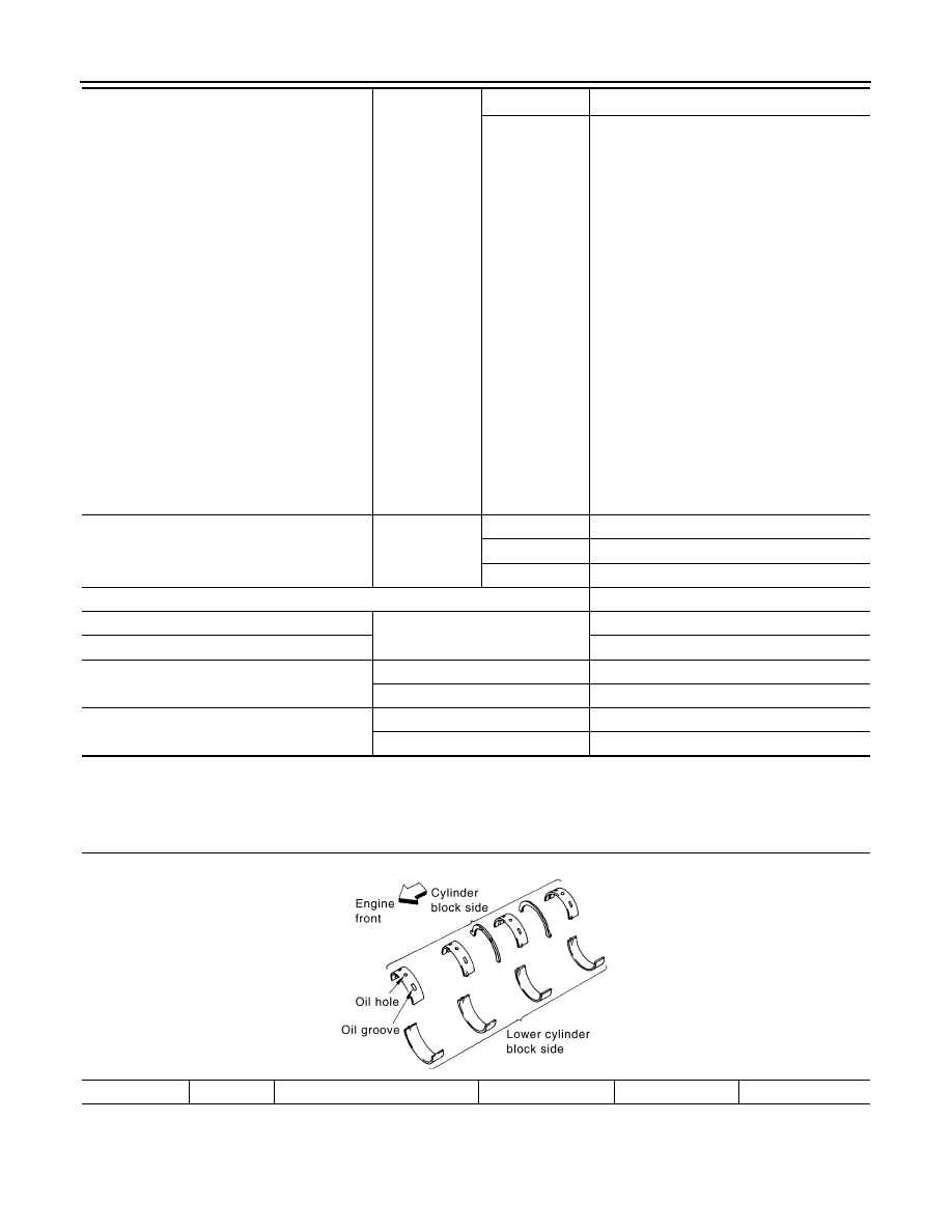
Grade number*
UPR/LWR
Thickness mm (in)
Width mm (in)
Identification color
Remarks
PBIC2969E
2010 Pathfinder