Nissan Pathfinder (2010 year). Manual - part 350


  Index      Manuals     Nissan Pathfinder (2010 year) - Service and Repair Manual


Search            copyright infringement  


Content      ..     348      349      350      351     ..


Nissan Pathfinder (2010 year). Manual - part 350


EC-892

< COMPONENT DIAGNOSIS >

[VK56DE]

POSITIVE CRANKCASE VENTILATION

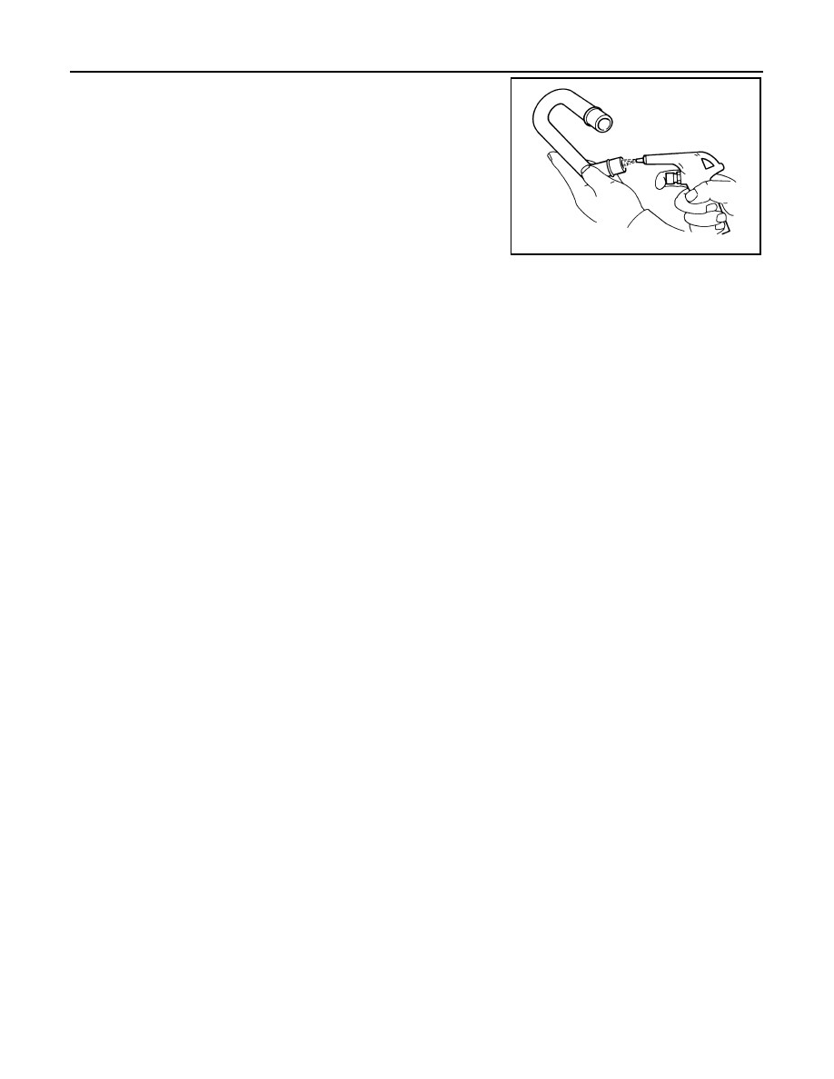
1. Check hoses and hose connections for leakage.
2. Disconnect all hoses and clean with compressed air. If any hose

cannot be freed of obstructions, replace.

S-ET277

2010 Pathfinder

REFRIGERANT PRESSURE SENSOR

EC-893

< COMPONENT DIAGNOSIS >

[VK56DE]

C

D

E

F

G

H

I

J

K

L

M

A

EC

N

P

O

REFRIGERANT PRESSURE SENSOR

Component Description

INFOID:0000000005257911

The refrigerant pressure sensor (1) is installed at the condenser of

the air conditioner system. The sensor uses an electrostatic volume

pressure transducer to convert refrigerant pressure to voltage. The

voltage signal is sent to ECM, and ECM controls cooling fan system.

Diagnosis Procedure

INFOID:0000000005257912

1.

CHECK REFRIGERANT PRESSURE SENSOR OVERALL FUNCTION

1. Start engine and warm it up to normal operating temperature.

2. Turn A/C switch and blower fan switch ON.

3. Check voltage between ECM terminal 70 and ground with CON-

SULT-III or tester.

OK or NG

OK

>>

INSPECTION END

NG

>> GO TO 2.

2.

CHECK GROUND CONNECTIONS

1. Turn A/C switch and blower fan switch OFF.

2. Turn ignition switch OFF.

3. Loosen and retighten ground screws on the body.

ALBIA0357ZZ

PBIB2657E

Voltage: 1.0 - 4.0 V

PBIB1188E

2010 Pathfinder

EC-894

< COMPONENT DIAGNOSIS >

[VK56DE]

REFRIGERANT PRESSURE SENSOR

Refer to 

EC-577, "Ground Inspection"

.

OK or NG

OK

>> GO TO 3.

NG

>> Repair or replace ground connections.

3.

CHECK REFRIGERANT PRESSURE SENSOR POWER SUPPLY CIRCUIT

1. Disconnect refrigerant pressure sensor (1) harness connector.

2. Turn ignition switch ON.

3. Check voltage between refrigerant pressure sensor terminal 1

and ground with CONSULT-III or tester.

OK or NG

OK

>> GO TO 5.

NG

>> GO TO 4.

4.

DETECT MALFUNCTIONING PART

Check the following.

• Harness connectors E5, F14

• Harness for open or short between ECM and refrigerant pressure sensor

>> Repair harness or connectors.

5.

CHECK REFRIGERANT PRESSURE SENSOR GROUND CIRCUIT FOR OPEN AND SHORT

1. Turn ignition switch OFF.

2. Disconnect ECM harness connector.

3. Check harness continuity between refrigerant pressure sensor terminal 3 and ECM terminal 67.

Refer to Wiring Diagram.

4. Also check harness for short to ground and short to power.
OK or NG

OK

>> GO TO 7.

NG

>> GO TO 6.

BBIA0539E

ALBIA0357ZZ

Voltage: Approximately 5 V

PBIB0188E

Continuity should exist.

2010 Pathfinder

REFRIGERANT PRESSURE SENSOR

EC-895

< COMPONENT DIAGNOSIS >

[VK56DE]

C

D

E

F

G

H

I

J

K

L

M

A

EC

N

P

O

6.

DETECT MALFUNCTIONING PART

Check the following.

• Harness connectors E5, F14

• Harness for open or short between ECM and refrigerant pressure sensor

>> Repair open circuit or short to ground or short to power in harness or connectors.

7.

CHECK REFRIGERANT PRESSURE SENSOR INPUT SIGNAL CIRCUIT FOR OPEN AND SHORT

1. Check harness continuity between ECM terminal 70 and refrigerant pressure sensor terminal 2.

Refer to Wiring Diagram.

2. Also check harness for short to ground and short to power.
OK or NG

OK

>> GO TO 9.

NG

>> GO TO 8.

8.

DETECT MALFUNCTIONING PART

Check the following.

• Harness connectors E5, F14

• Harness for open or short between ECM and refrigerant pressure sensor

>> Repair open circuit or short to ground or short to power in harness or connectors.

9.

CHECK INTERMITTENT INCIDENT

Refer to 

GI-37, "Intermittent Incident"

.

OK or NG

OK

>> Replace refrigerant pressure sensor.

NG

>> Repair or replace malfunctioning part.

Continuity should exist.

2010 Pathfinder

EC-896

< ECU DIAGNOSIS >

[VK56DE]

ECM

ECU DIAGNOSIS

ECM

CONSULT-III Reference Value in Data Monitor Mode

INFOID:0000000005257913

Remarks:

z

 Specification data are reference values.

z

 Specification data are output/input values which are detected or supplied by the ECM at the connector.

* Specification data may not be directly related to their components signals/values/operations.

i.e. Adjust ignition timing with a timing light before monitoring IGN TIMING, because the monitor may show

the specification data in spite of the ignition timing not being adjusted to the specification data. This IGN TIM-

ING monitors the data calculated by the ECM according to the signals input from the camshaft position sensor

and other ignition timing related sensors.

MONITOR ITEM

CONDITION

SPECIFICATION

ENG SPEED

• Run engine and compare CONSULT-III value with the tachometer indication.

Almost the same speed as the 
tachometer indication.

MAS A/F SE-B1

See 

EC-566, "Description"

.

B/FUEL SCHDL

See 

EC-566, "Description"

.

A/F ALPHA-B1
A/F ALPHA-B2

See 

EC-566, "Description"

.

COOLAN TEMP/S

• Engine: After warming up

More than 70

°

C (158

°

F)

A/F SEN1 (B1)
A/F SEN1 (B2)

• Engine: After warming up

Maintaining engine speed at 2,000 
rpm

Fluctuates around 2.2 V

HO2S2 (B1)
HO2S2 (B2)

• Revving engine from idle to 3,000 rpm quickly after the following conditions 

are met.

• After keeping engine speed between 3,500 and 4,000 rpm for 1 minute and 

at idle for 1 minute under no load

0 - 0.3 V 

←→

 Approx. 0.6 - 1.0 

V

HO2S2 MNTR (B1)
HO2S2 MNTR (B2)

• Revving engine from idle to 3,000 rpm quickly after the following conditions 

are met.

- Engine: After warming up
- Keeping engine speed between 3,500 and 4,000 rpm for 1 minute and at idle 

for 1 minute under no load

LEAN 

←→

 RICH

VHCL SPEED SE

• Turn drive wheels and compare CONSULT-III value with the speedometer 

indication.

Almost the same speed as the 
speedometer indication

BATTERY VOLT

• Ignition switch: ON (Engine stopped)

11 - 14 V

ACCEL SEN 1

• Ignition switch: ON

(Engine stopped)

Accelerator pedal: Fully released

0.65 - 1.87 V

Accelerator pedal: Fully depressed

More than 4.3 V

ACCEL SEN 2*

1

• Ignition switch: ON

(Engine stopped)

Accelerator pedal: Fully released

0.56 - 0.96 V

Accelerator pedal: Fully depressed

More than 4.0 V

TP SEN 1-B1
TP SEN 2-B1*

1

• Ignition switch: ON

(Engine stopped)

• Selector lever: D

Accelerator pedal: Fully released

More than 0.36 V

Accelerator pedal: Fully depressed

Less than 4.75 V

EVAP SYS PRES

• Ignition switch: ON

Approx. 1.8 - 4.8 V

START SIGNAL

• Ignition switch: ON 

 START 

 ON

OFF 

 ON 

 OFF

CLSD THL POS

• Ignition switch: ON

(Engine stopped)

Accelerator pedal: Fully released

ON

Accelerator pedal: Slightly depressed

OFF

AIR COND SIG

• Engine: After warming up, idle the 

engine

Air conditioner switch: OFF

OFF

Air conditioner switch: ON
(Compressor: Operates.)

ON

P/N POSI SW

• Ignition switch: ON

Selector lever: P or N position

ON

Selector lever: Except above position

OFF

2010 Pathfinder

ECM

EC-897

< ECU DIAGNOSIS >

[VK56DE]

C

D

E

F

G

H

I

J

K

L

M

A

EC

N

P

O

PW/ST SIGNAL

• Engine: After warming up, idle the 

engine

Steering wheel: Not being turned
(Forward direction)

OFF

Steering wheel: Being turned

ON

LOAD SIGNAL

• Ignition switch: ON

Rear window defogger switch is ON 
and/or lighting switch is in 2nd.

ON

Rear window defogger switch is OFF 
and lighting switch is OFF.

OFF

IGNITION SW

• Ignition switch: ON 

 OFF 

 ON

ON 

 OFF 

 ON

HEATER FAN SW

• Engine: After warming up, idle the 

engine

Heater fan control switch: OFF

OFF

Heater fan control switch: ON

ON

BRAKE SW

• Ignition switch: ON

Brake pedal: Fully released

OFF

Brake pedal: Slightly depressed

ON

INJ PULSE-B1
INJ PULSE-B2

• Engine: After warming up
• Selector lever: P or N position
• Air conditioner switch: OFF
• No  load

Idle

2.0 - 2.8 msec

2,000 rpm

1.9 - 2.9 msec

IGN TIMING

• Engine: After warming up
• Selector lever: P or N position
• Air conditioner switch: OFF
• No  load

Idle

10

°

 - 20

°

BTDC

2,000 rpm

25

°

 - 45

°

BTDC

CAL/LD VALUE

• Engine: After warming up
• Selector lever: P or N position
• Air conditioner switch: OFF
• No  load

Idle

14% - 33%

2,500 rpm

12% - 25%

MASS AIRFLOW

• Engine: After warming up
• Selector lever: P or N position
• Air conditioner switch: OFF
• No  load

Idle

3.0 - 9.0 g·m/s

2,500 rpm

9.0 - 28.0 g·m/s

PURG VOL C/V

• Engine: After warming up
• Selector lever: P or N position
• Air conditioner switch: OFF
• No  load

Idle
(Accelerator pedal: Not depressed 
even slightly, after engine starting.)

0%

2,000 rpm

INT/V TIM (B1)
INT/V TIM (B2)

• Engine: After warming up
• Selector lever: P or N position
• Air conditioner switch: OFF
• No  load

Idle

5

°

 - 5

°

CA

2,000 rpm

Approx. 0

°

 - 20

°

CA

INT/V SOL (B1)
INT/V SOL (B2)

• Engine: After warming up
• Selector lever: P or N position
• Air conditioner switch: OFF
• No  load

Idle

0% - 2%

2,000 rpm

Approx. 25% - 50%

AIR COND RLY

• Engine: After warming up, idle the 

engine

Air conditioner switch: OFF

OFF

Air conditioner switch: ON
(Compressor: Operates)

ON

FUEL PUMP RLY

• For 1 second after turning ignition switch ON
• Engine running or cranking

ON

• Except above conditions

OFF

VENT CONT/V

• Ignition switch: ON

OFF

THRTL RELAY

• Ignition switch: ON

ON

MONITOR ITEM

CONDITION

SPECIFICATION

2010 Pathfinder

EC-898

< ECU DIAGNOSIS >

[VK56DE]

ECM

COOLING FAN

• Engine: After warming up, idle the 

engine

• Air conditioner switch: OFF

Engine coolant temperature: 97

°

(207

°

F) or less

OFF

Engine coolant temperature: Between 
98

°

C (208

°

F) and 100

°

C (212

°

F)

LOW

Engine coolant temperature: 101

°

(214

°

F) or more

HI

HO2S2 HTR (B1)
HO2S2 HTR (B2)

• Engine speed is below 3,600 rpm after the following conditions are met.
- Engine: After warming up
- Keeping the engine speed between 3,500 and 4,000 rpm for 1 minute and 

at idle for 1 minute under no load

ON

• Engine speed: Above 3,600 rpm

OFF

I/P PULLY SPD

• Vehicle speed: More than 20 km/h (12 MPH)

Almost the same speed as the 
tachometer indication

VEHICLE SPEED

• Turn drive wheels and compare CONSULT-III value with the speedometer 

indication.

Almost the same speed as the 
speedometer indication

TRVL AFTER MIL

• Ignition switch: ON

Vehicle has traveled after MIL has illu-
minated.

0 - 65,535 km
(0 - 40,723 mile)

A/F S1 HTR (B1)
A/F S1 HTR (B2)

• Engine: After warming up, idle the engine

4 - 100%

AC PRESS SEN

• Engine: Idle
• Both A/C switch and blower fan switch: ON (Compressor operates.)

1.0 - 4.0 V

VHCL SPEED SE

• Turn drive wheels and compare CONSULT-III value with the speedometer 

indication.

Almost the same speed as the 
speedometer indication

SET VHCL SPD

• Engine: Running

ASCD: Operating.

The preset vehicle speed is 
displayed.

MAIN SW

• Ignition switch: ON

MAIN switch: Pressed

ON

MAIN switch: Released

OFF

CANCEL SW

• Ignition switch: ON

CANCEL switch: Pressed

ON

CANCEL switch: Released

OFF

RESUME/ACC SW

• Ignition switch: ON

RESUME/ACCELERATE switch: 
Pressed

ON

RESUME/ACCELERATE switch: Re-
leased

OFF

SET SW

• Ignition switch: ON

SET/COAST switch: Pressed

ON

SET/COAST switch: Released

OFF

BRAKE SW1

• Ignition switch: ON

Brake pedal: Fully released

ON

Brake pedal: Slightly depressed

OFF

BRAKE SW2

• Ignition switch: ON

Brake pedal: Fully released

OFF

Brake pedal: Slightly depressed

ON

CRUISE LAMP

• Ignition switch: ON

MAIN switch: Pressed at the 1st time 

 at the 2nd time

ON 

 OFF

SET LAMP

• MAIN switch: ON
• Vehicle speed: Between 40 km/h 

(25 MPH) and 144 km/h (89 MPH)

ASCD: Operating

ON

ASCD: Not operating

OFF

ALT DUTY

• Engine: Idle

0 - 80%

BAT CUR SEN

• Engine speed: Idle
• Battery: Fully charged*

2

• Selector lever: P or N position
• Air conditioner switch: OFF
• No  load

Approx. 2,600 - 3,500 mV

MONITOR ITEM

CONDITION

SPECIFICATION

2010 Pathfinder

ECM

EC-899

< ECU DIAGNOSIS >

[VK56DE]

C

D

E

F

G

H

I

J

K

L

M

A

EC

N

P

O

*1: Accelerator pedal position sensor 2 signal and throttle position sensor 2 signal are converted by ECM internally. Thus, they differ
from ECM terminals voltage signal.
*2: Before measuring the terminal voltage, confirm the battery is fully charged. Refer to 

PG-5, "How to Handle Battery"

.

ECM Harness Connector Terminal Layout

INFOID:0000000005257914

ECM Terminal and Reference Value

INFOID:0000000005257915

PREPARATION

ECM is located in the engine room passenger side behind battery.

ECM INSPECTION TABLE

Specification data are reference values and are measured between each terminal and ground.

Pulse signal is measured by CONSULT-III.

CAUTION:

Never use ECM ground terminals when measuring input/output voltage. Doing so may result in dam-

age to the ECMs transistor. Use a ground other than ECM terminals, such as the ground.

ALT DUTY SIG

• Power generation voltage variable control: Operating

ON

• Power generation voltage variable control: Not operating

OFF

MONITOR ITEM

CONDITION

SPECIFICATION

PBIB3368E

BBIA0386E

TER-

MI-

NAL 

NO.

WIRE 

COLOR

ITEM

CONDITION

DATA (DC Voltage)

1

BR

ECM ground

[Engine is running]

• Idle speed

Body ground

2

G

A/F sensor 1 heater (bank 1)

[Engine is running]

Warm-up condition

• Idle speed

(More than 140 seconds after starting 
engine)

Approximately 2.9 - 8.8 V

3

V

Throttle control motor power sup-
ply

[Ignition switch: ON]

BATTERY VOLTAGE
(11 - 14 V)

PBIA8148J

2010 Pathfinder


Content      ..     348      349      350      351     ..