Nissan Pathfinder (2010 year). Manual - part 318
EC-636
< COMPONENT DIAGNOSIS >
[VK56DE]
P0131, P0151 A/F SENSOR 1
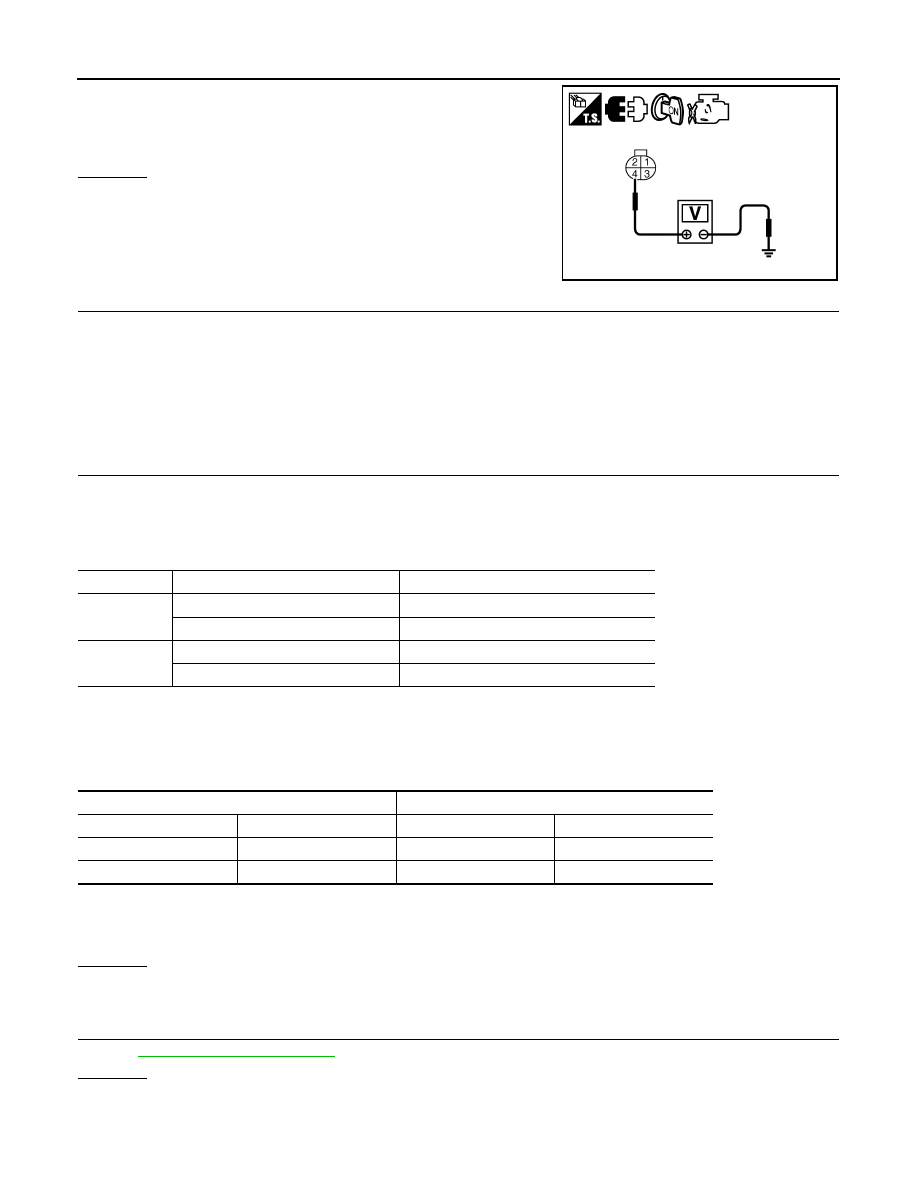
3. Check voltage between A/F sensor 1 terminal 4 and ground with
CONSULT-III or tester.
OK or NG
OK
>> GO TO 4.
NG
>> GO TO 3.
3.
DETECT MALFUNCTIONING PART
Check the following.
• Harness connectors E2, F32
• IPDM E/R harness connector E119
• 15 A fuse (No. 54)
• Harness for open or short between A/F sensor 1 and IPDM E/R
>> Repair or replace harness or connectors.
4.
CHECK A/F SENSOR 1 INPUT SIGNAL CIRCUIT FOR OPEN AND SHORT
1. Turn ignition switch OFF.
2. Disconnect ECM harness connector.
3. Check harness continuity between A/F sensor 1 terminals and ECM terminals as per the following.
Refer to Wiring Diagram.
4. Check harness continuity between the following terminals and ground.
Refer to Wiring Diagram.
5. Also check harness for short to power.
OK or NG
OK
>> GO TO 5.
NG
>> Repair open circuit or short to ground or short to power in harness or connectors.
5.
CHECK INTERMITTENT INCIDENT
Perform
GI-37, "Intermittent Incident"
.
OK or NG
OK
>> GO TO 6.
NG
>> Repair or replace malfunctioning part.
Voltage: Battery voltage
PBIB3308E
A/F sensor 1 terminal
ECM terminal
Bank1
1
35
2
56
Bank 2
1
16
2
75
Continuity should exist.
Bank 1
Bank 2
A/F sensor 1 terminal
ECM terminal
A/F sensor 1 terminal
ECM terminal
1
35
1
16
2
56
2
75
Continuity should not exist.
2010 Pathfinder