Nissan Pathfinder (2010 year). Manual - part 232


  Index      Manuals     Nissan Pathfinder (2010 year) - Service and Repair Manual


Search            copyright infringement  


Content      ..     230      231      232      233     ..


Nissan Pathfinder (2010 year). Manual - part 232


REAR FINAL DRIVE

DLN-429

< DISASSEMBLY AND ASSEMBLY >

[REAR FINAL DRIVE: R200]

C

E

F

G

H

I

J

K

L

M

A

B

DLN

N

O

P

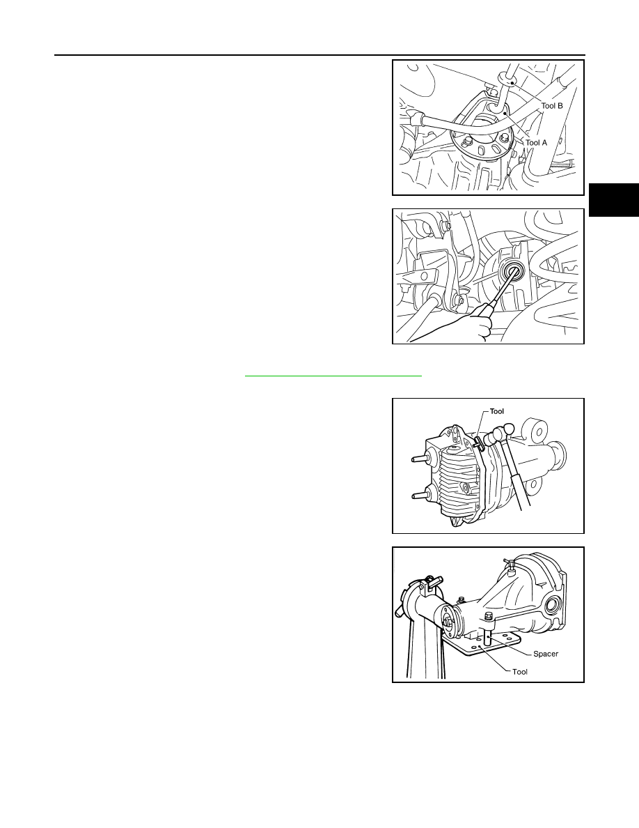
2. Remove the side flange using Tools.

NOTE:

Circular clip installation position: Rear final drive side

3. Remove the side oil seal using suitable tool.

CAUTION:

Do not to damage gear carrier.

Differential Assembly

1. Remove the side flanges. Refer to 

DLN-419, "Removal and Installation"

.

2. Remove the carrier cover bolts.
3. Remove the carrier cover bolts and separate the carrier cover

from the gear carrier using Tool.

CAUTION:

• Do not damage the mating surface.

• Do not insert flat-bladed screwdriver, this will damage the

mating surface.

4. Mount the carrier on the Tool using two 45 mm (1.77 in) spacers.

Tool numbers

A: KV40104100 ( — )
B: ST36230000 (J-25840-A)

WDIA0115E

SDIA0495E

Tool number

: KV10111100 (J-37228)

WDIA0123E

Tool number

: KV38100800 (J-25604-01)

SPD888

2010 Pathfinder

DLN-430

< DISASSEMBLY AND ASSEMBLY >

[REAR FINAL DRIVE: R200]

REAR FINAL DRIVE

5. For proper reinstallation, paint matching marks on one side of

the side bearing cap and gear carrier.

CAUTION:

• For matching marks, use paint. Do not damage side bear-

ing cap or gear carrier.

• Side bearing caps are line-board during manufacture. The

matching marks are used to reinstall them in their original

positions.

6. Remove the side bearing caps.

7. Lift the differential case assembly out using Tool.

CAUTION:

• Keep side bearing outer races together with inner race.

Do not mix them up.

• Keep side bearing adjusting washers together with side

bearings.

SDIA1795E

S-PD343

Tool number

: HT72400000 ( — )

S-PD344

SPD919

2010 Pathfinder

REAR FINAL DRIVE

DLN-431

< DISASSEMBLY AND ASSEMBLY >

[REAR FINAL DRIVE: R200]

C

E

F

G

H

I

J

K

L

M

A

B

DLN

N

O

P

8. Remove the side bearing inner races using Tools.

CAUTION:

• Engage Tool jaws in bearing groove to prevent damage.

• Place copper plates between the side bearing and drive

gear and the vise to prevent damage.

• Do not remove side bearing inner race unless it is being

replaced.

9. For proper reinstallation, paint matching marks on the differential

case and drive gear.

CAUTION:

Use paint for matching marks. Do not damage differential

case or drive gear.

10. Remove the drive gear bolts.
11. Tap the drive gear off the differential case using suitable tool.

CAUTION:

Tap evenly all around to keep drive gear from bending.

12. Remove the lock pin of the pinion mate shaft from the drive gear

side using suitable tool.

13. Remove the pinion mate shaft.

Tool number  A: ST33051001 (J-22888-20)

 B: ST33061000 (J-8107-2)

SPD920

PDIA0496E

WDIA0132E

SDIA0031J

2010 Pathfinder

DLN-432

< DISASSEMBLY AND ASSEMBLY >

[REAR FINAL DRIVE: R200]

REAR FINAL DRIVE

14. Turn the pinion mate gear, then remove the pinion mate gear,

pinion mate thrust washer, side gear and side gear thrust

washer from the differential case.

Drive Pinion Assembly

1. Remove the differential assembly. Refer to 

DLN-422, "Removal and Installation"

.

2. Remove the drive pinion lock nut using suitable tool.
3. Put matching marks on the companion flange and drive pinion

using paint.

CAUTION:

Use paint to make the matching marks. Do not damage the

companion flange or drive pinion.

4. Remove the companion flange using suitable tool.

5. Press the drive pinion assembly (with rear inner bearing race

and collapsible spacer) out of the gear carrier.

CAUTION:

Do not drop drive pinion assembly.

6. Remove the front oil seal.

CAUTION:

Do not damage gear carrier.

7. Remove the drive pinion front bearing inner race.

SDIA0032J

SDIA1144E

SDIA1132E

SPD892

2010 Pathfinder

REAR FINAL DRIVE

DLN-433

< DISASSEMBLY AND ASSEMBLY >

[REAR FINAL DRIVE: R200]

C

E

F

G

H

I

J

K

L

M

A

B

DLN

N

O

P

8. Remove the drive pinion rear bearing inner race and drive pinion

height adjusting washer using Tool.

9. Remove the drive pinion front and rear bearing outer races by

tapping them uniformly using suitable tool.

CAUTION:

Do not damage gear carrier.

INSPECTION AFTER DISASSEMBLY

Clean the disassembled parts. Then inspect the parts for wear or damage. If wear or damage are found, follow

the measures below.

Drive Pinion and Drive Gear

• If the drive pinion and drive gear teeth do not mesh or line-up correctly, determine the cause and adjust,

repair, or replace as necessary.

• If the drive pinion or drive gear are worn, cracked, damaged, pitted or chipped (by friction) noticeably,

replace with new drive pinion and drive gear.

• Drive pinion and drive gear are supplied in matched sets only. Matching numbers on both drive pinion and

drive gear are etched for verification. If a new drive pinion and drive gear set are being used, verify the num-

bers of each drive pinion and drive gear before proceeding with assembly.

Bearing

• If bearings are chipped (by friction), pitted, worn, rusted, scratched, or unusual noise is coming from bearing,

replace with new bearing assembly (as a new set).

• Bearing must be replaced with a new one whenever disassembled.

Side Gear and Pinion Mate Gear

• If any cracks or damage are found on the surface of the teeth, replace with new one.

• If any worn or chipped marks are found on the side of the side gear and pinion mate gear which contact the

thrust washer, replace with new one.

• Replace both side gear and pinion mate gear as a set when replacing side gear or pinion mate gear.

Side Gear Thrust Washer and Pinion Mate Thrust Washer

• If any chips (by friction), damage, or unusual wear are found, replace with new one.

Gear Carrier

• If any wear or cracks are found on the contact sides of gear carrier, replace with new one.

Companion Flange

• If any chips (about 0.1mm, 0.004 in) or other damage on the companion flange surface which contacts the

front oil seal lips are found, replace with new one.

ADJUSTING AND SELECTING WASHERS

Side Gear Back Clearance

• Assemble the differential parts if they are disassembled. Refer to 

DLN-425, "Exploded View"

.

Tool number

: ST30031000 (J-22912-01)

S-PD179

SDIA0817E

2010 Pathfinder

DLN-434

< DISASSEMBLY AND ASSEMBLY >

[REAR FINAL DRIVE: R200]

REAR FINAL DRIVE

1. Place the differential case straight up so that the side gear to be

measured is upward.

2. Using feeler gauges, measure the clearance between the side

gear back and differential case at three different points, while

rotating the side gear. Average the three readings to calculate

the clearance. (Measure the clearance of the other side as well.)

• If the side gear back clearance is outside of the specification,

use a thicker or thinner side gear thrust washer to adjust.

Refer to 

DLN-444, "Inspection and Adjustment"

.

CAUTION:

• Insert feeler gauges with the same thickness on both

sides to prevent side gear from tilting.

• Each gear should rotate smoothly without excessive

resistance during differential motion.

• Select a side gear thrust washer for right and left individually.

NOTE:

Side gear back clearance is clearance between side gear and differential case for adjusting side gear

backlash.

Side Bearing Preload Torque

• A selection of side bearing adjusting washers is required for successful completion of this procedure.
1. Apply differential gear oil to the side bearings, and install the dif-

ferential case assembly with the side bearing outer races into

the gear carrier.

CAUTION:

Do not reuse side bearing outer race when replacing side

bearing inner race (replace as a set).

PDIA0460E

Side gear back clearance: Refer to 

DLN-444, "Inspec-

tion and Adjustment"

If the side gear back clearance is greater than 
specification:

Use a thicker side gear thrust washer.

If the side gear back clearance is less than spec-
ification:

Use a thinner side gear thrust washer.

PDIA0576E

SPD527

2010 Pathfinder

REAR FINAL DRIVE

DLN-435

< DISASSEMBLY AND ASSEMBLY >

[REAR FINAL DRIVE: R200]

C

E

F

G

H

I

J

K

L

M

A

B

DLN

N

O

P

2. Insert the left and right original side bearing adjusting washers in

place between side bearings and gear carrier.

3. Align the matching mark on the side bearing cap with the match-

ing mark on the gear carrier.

4. Install the side bearing caps and tighten the side bearing cap

bolts to the specified torque. Refer to 

DLN-425, "Exploded

View"

.

5. Turn the differential assembly several times to seat the side

bearings.

6. To determine side bearing preload torque, measure the pulling

force of the differential assembly at the drive gear bolt using

Tool.

NOTE:

If pulling force of the differential assembly at the drive gear bolt

is within specification, side bearing preload torque will also be

within specification. Refer to 

DLN-444, "Inspection and Adjustment"

.

7. If the pulling force is outside the specification, use a thicker or

thinner side bearing adjusting washer to adjust. Refer to 

DLN-

444, "Inspection and Adjustment"

.

CAUTION:

Select a side bearing adjusting washer for right and left

individually.

8. Record the total amount of washer thickness required for the correct side bearing preload torque.

Drive Pinion Height

SPD924

SDIA1795E

Tool number

 (J-8129)

Specification

Refer to 

DLN-444, "Inspection and Ad-

justment"

SPD194A

If the pulling force is less than the specification:

Use a thicker side bearing adjusting washer.

If the pulling force is greater than the specification:

Use a thinner side bearing adjusting washer.

SPD772

2010 Pathfinder

DLN-436

< DISASSEMBLY AND ASSEMBLY >

[REAR FINAL DRIVE: R200]

REAR FINAL DRIVE

1. Make sure all parts are clean and that the bearings are well

lubricated.

2. Assemble the drive pinion bearings onto the Tool.

Drive pinion front bearing;

 make sure the J-34309-3 drive

pinion front bearing seat is secured tightly against the J-

34309-2 gauge anvil. Then turn the J-34309-5 drive pinion

front bearing pilot to secure the drive pinion bearing in its

proper position.

Drive pinion rear bearing;

 the J-34309-8 drive pinion rear

bearing pilot is used to center the drive pinion rear bearing

only. The J-34309-4 drive pinion rear bearing locking seat is

used to lock the drive pinion rear bearing to the assembly.

Installation of J-34309-9 and J-34309-16;

 place a suitable

2.5 mm (0.098 in) thick plain washer between J-34309-9 and

J-34309-16. Both surfaces of J-34309-9 and J-34309-16 must

be parallel with a clearance of 2.5 mm (0.098 in).

3. Install the drive pinion rear bearing inner race into the gear car-

rier. Then insert the drive pinion height adjusting washer selec-

tor tool, J-34309-1, gauge screw assembly.

4. Assemble the drive pinion front bearing inner race and the J-

34309-2 gauge anvil. Assemble them together with the J-34309-

1 gauge screw in the gear carrier. Make sure that the drive pin-

ion height gauge plate, J-34309-16, will turn a full 360

°

. Tighten

the two sections together by hand.

Tool number

 (J-34309)

SPD769

SPD197A

SPD893

SPD199A

2010 Pathfinder


Content      ..     230      231      232      233     ..