Nissan Pathfinder (2010 year). Manual - part 188


  Index      Manuals     Nissan Pathfinder (2010 year) - Service and Repair Manual


Search            copyright infringement  


Content      ..     186      187      188      189     ..


Nissan Pathfinder (2010 year). Manual - part 188


P1827 CLUTCH PRESSURE SWITCH

DLN-77

< COMPONENT DIAGNOSIS >

[TRANSFER: ATX14B]

C

E

F

G

H

I

J

K

L

M

A

B

DLN

N

O

P

P1827 CLUTCH PRESSURE SWITCH

Description

INFOID:0000000005258294

Improper signal from the clutch pressure switch is input due to open or short circuit.  Also, a malfunction may

have occurred in clutch pressure switch or hydraulic circuit.

DTC Logic

INFOID:0000000005258295

DTC DETECTION LOGIC

DTC CONFIRMATION PROCEDURE

1.

DTC CONFIRMATION PROCEDURE

1. Turn ignition switch ON.

2. Perform self-diagnosis.
Is DTC P1827 displayed?

YES

>> Perform diagnosis procedure. Refer to 

DLN-77, "Diagnosis Procedure"

.

NO

>> Inspection End.

Diagnosis Procedure

INFOID:0000000005258296

Regarding Wiring Diagram information, refer to 

DLN-95, "Wiring Diagram - ALL-MODE 4WD SYSTEM -"

.

1.

CHECK CLUTCH PRESSURE SWITCH SIGNAL

With CONSULT-III

1. Start engine.

2. Select DATA MONITOR mode for ALL MODE AWD/4WD with CONSULT-III.

3. Read out ON/OFF switching action of the CL PRES SW while operating 4WD shift switch.
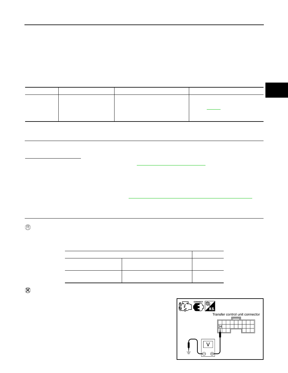
Without CONSULT-III

1. Start engine.

2. Check voltage between transfer control unit harness connector

terminals and ground.

DTC

CONSULT-III

Diagnostic item is detected when...

Reference

[P1827]

CLUTCH PRES SW

• Improper signal from clutch pressure 

switch is input due to open or short cir-
cuit.

• Malfunction occurs in clutch pressure 

switch or hydraulic circuit.

Refer to 

DLN-77

.

Condition

Display value

• Ignition switch: ON
• A/T selector lever D position

4WD shift switch: AUTO or 4H (Wait 
function is not operating.)

ON

Ignition switch: ON

4WD shift switch: 2WD (Wait function 
is not operating.)

OFF

SDIA2746E

2010 Pathfinder

DLN-78

< COMPONENT DIAGNOSIS >

[TRANSFER: ATX14B]

P1827 CLUTCH PRESSURE SWITCH

Are inspection results normal?

YES

>> GO TO 5.

NO

>> GO TO 2.

2.

CHECK HARNESS BETWEEN TRANSFER CONTROL UNIT AND CLUTCH PRESSURE SWITCH

1. Turn ignition switch OFF. (Stay for at least 5 seconds.)

2. Disconnect transfer control unit harness connector and the transfer terminal cord assembly harness con-

nector.

3. Check continuity between transfer control unit harness connec-

tor M153 terminal 34 and transfer terminal cord assembly har-

ness connector F56 terminal 7

Also check harness for short to ground and short to power.

Are inspection results normal?

YES 

>> GO TO 3.

NO

>> Repair or replace damaged parts.

3.

CHECK TRANSFER CONTROL UNIT

Check transfer control unit input/output signal. Refer to 

DLN-87, "Reference Value"

.

Are inspection results normal?

YES

>> GO TO 4.

NO

>> Check transfer control unit pin terminals for damage or loose connection with the harness connec-

tor. If any items are damaged, repair or replace damaged parts.

4.

CHECK CLUTCH PRESSURE SWITCH

1. Turn ignition switch OFF. (Stay for at least 5 seconds.)

2. Remove clutch pressure switch. Refer to 

DLN-19, "Component Parts Location"

.

3. Push and release clutch pressure switch and check continuity

between terminal 7 and ground.

Are inspection results normal?

YES 

>> GO TO 5.

NO

>> Replace clutch pressure switch.

5.

CHECK DTC

Perform the self-diagnosis, after driving a vehicle for a while.
Are inspection results normal?

YES

>> GO TO 6.

NO

>> Replace transfer control unit. Refer to 

DLN-138, "Removal and Installation"

.

Connector

Terminal

Condition

Voltage 

(Approx.)

M153

34 - 

Ground

• Ignition switch: ON
• A/T selector lever D 

position

4WD shift switch: 
AUTO or 4H (Wait 
function is not op-
erating.)

0V

Ignition switch: ON

4WD shift switch: 
2WD (Wait function 
is not operating.)

Battery 
voltage

Continuity should exist.

SDIA2747E

Terminal

Condition

Continuity

7 - 

Ground

Push clutch pressure switch

Yes

Release clutch pressure switch

No

WDIA0171E

2010 Pathfinder

P1827 CLUTCH PRESSURE SWITCH

DLN-79

< COMPONENT DIAGNOSIS >

[TRANSFER: ATX14B]

C

E

F

G

H

I

J

K

L

M

A

B

DLN

N

O

P

6.

CRUISE TEST

Perform cruise test. Refer to 

DLN-10, "Preliminary Check"

.

Are inspection results normal?

YES

>> Inspection End.

NO

>> Perform the applicable trouble diagnosis.

Component Inspection

INFOID:0000000005258297

1. Turn ignition switch OFF. (Stay for at least 5 seconds.)
2. Remove clutch pressure switch. Refer to 

DLN-19, "Component Parts Location"

.

3. Push and release clutch pressure switch and check continuity

between terminal 7 and ground.

4. If the inspection results are abnormal replace the clutch pres-

sure switch.

Terminal

Condition

Continuity

7 - Ground

Push clutch pressure switch

Yes

Release clutch pressure switch

No

WDIA0171E

2010 Pathfinder

DLN-80

< COMPONENT DIAGNOSIS >

[TRANSFER: ATX14B]

P1828 LINE PRESSURE SWITCH

P1828 LINE PRESSURE SWITCH

Description

INFOID:0000000005258298

Improper signal from line pressure switch is input due to open or short circuit.  Also, a malfunction may have

occurred in the line pressure switch or hydraulic circuit.

DTC Logic

INFOID:0000000005258299

DTC DETECTION LOGIC

DTC CONFIRMATION PROCEDURE

1.

DTC CONFIRMATION PROCEDURE

1. Turn ignition switch ON.

2. Perform self-diagnosis.
Is DTC P1828 displayed?

YES

>> Perform diagnosis procedure. Refer to 

DLN-80, "Diagnosis Procedure"

.

NO

>> Inspection End.

Diagnosis Procedure

INFOID:0000000005258300

Regarding Wiring Diagram information, refer to 

DLN-95, "Wiring Diagram - ALL-MODE 4WD SYSTEM -"

.

1.

CHECK LINE PRESSURE SWITCH SIGNAL

With CONSULT-III

1. Start engine.

2. Select DATA MONITOR mode for ALL MODE AWD/4WD with CONSULT-III.

3. Read out ON/OFF switching action of LINE PRES SW while operating 4WD shift switch.

Without CONSULT-III

1. Start engine.

DTC

CONSULT-III

Diagnostic item is detected when...

Reference

[P1828]

LINE PRES SW

• Improper signal from line pressure 

switch is input due to open or short cir-
cuit.

• Malfunction occurs in line pressure 

switch or hydraulic circuit.

Refer to 

DLN-80

.

Condition

Display value

• A/T selector lever D position
• 4WD shift switch: AUTO

ON

• Except the above
• The vehicle has been left 

at room temperature for 5 
minutes and more with ig-
nition switch in OFF posi-
tion.

• Ignition switch: ON
• A/T selector lever: P or N position
• 4WD shift switch: other than 

AUTO

OFF

2010 Pathfinder

P1828 LINE PRESSURE SWITCH

DLN-81

< COMPONENT DIAGNOSIS >

[TRANSFER: ATX14B]

C

E

F

G

H

I

J

K

L

M

A

B

DLN

N

O

P

2. Check voltage between transfer control unit harness connector

terminals and ground.

Are inspection results normal?

YES

>> GO TO 5.

NO

>> GO TO 2.

2.

CHECK HARNESS BETWEEN TRANSFER CONTROL UNIT AND LINE PRESSURE SWITCH

1. Turn ignition switch OFF. (Stay for at least 5 seconds.)

2. Disconnect transfer control unit harness connector and the transfer terminal cord assembly harness con-

nector.

3. Check continuity between transfer control unit harness connec-

tor M153 terminal 35 and transfer terminal cord assembly har-

ness connector F56 terminal 1.

Also check harness for short to ground and short to power.

Are inspection results normal?

YES 

>> GO TO 3.

NO

>> Repair or replace damaged parts.

3.

CHECK TRANSFER CONTROL UNIT

Check transfer control unit input/output signal. Refer to 

DLN-87, "Reference Value"

.

Are inspection results normal?

YES

>> GO TO 4.

NO

>> Check the following. If any items are damaged, repair or replace damaged parts.

• Transfer control unit pin terminals for damage or loose connection with harness connector.

• Transfer control unit. Refer to 

DLN-138, "Removal and Installation"

.

4.

CHECK LINE PRESSURE SWITCH

1. Turn ignition switch OFF. (Stay for at least 5 seconds.)

2. Remove line pressure switch. Refer to 

DLN-19, "Component Parts Location"

.

3. Push and release line pressure switch and check continuity

between terminal 1 and ground.

Are inspection results normal?

YES 

>> GO TO 5.

NO

>> Replace line pressure switch.

Connector

Terminal

Condition

Voltage 

(Approx.)

M153

35 - 

Ground

• A/T selector lever D 

position

4WD shift switch:  
AUTO

0V

• Except the above
• The vehicle has 

been left at room 
temperature for 5 
minutes and more 
with ignition switch 
in OFF position.

• Ignition switch: 

ON

• A/T selector le-

ver: P or N posi-
tion

• 4WD shift 

switch: other 
than AUTO

Battery 
voltage

SDIA2751E

Continuity should exist.

SDIA2752E

Terminal

Condition

Continuity

1 - 

Ground

Push line pressure switch

Yes

Release line pressure switch

No

WDIA0172E

2010 Pathfinder

DLN-82

< COMPONENT DIAGNOSIS >

[TRANSFER: ATX14B]

P1828 LINE PRESSURE SWITCH

5.

CHECK DTC

Perform the self-diagnosis, after driving a vehicle for a while.
Are inspection results normal?

YES

>> GO TO 6.

NO

>> Replace transfer control unit.

6.

CRUISE TEST

Perform cruise test. Refer to 

DLN-10, "Preliminary Check"

.

Are inspection results normal?

YES

>> Inspection End.

NO

>> Perform the applicable trouble diagnosis.

Component Inspection

INFOID:0000000005258301

1. Turn ignition switch OFF. (Stay for at least 5 seconds.)
2. Remove line pressure switch. Refer to 

DLN-19, "Component Parts Location"

.

3. Push and release line pressure switch and check continuity

between terminal 1 and ground.

4. If the inspection results are abnormal, replace the line pressure

switch.

Terminal

Condition

Continuity

1 - Ground

Push line pressure switch

Yes

Release line pressure switch

No

WDIA0172E

2010 Pathfinder

P1829 THROTTLE POSITION SIGNAL (ECM)

DLN-83

< COMPONENT DIAGNOSIS >

[TRANSFER: ATX14B]

C

E

F

G

H

I

J

K

L

M

A

B

DLN

N

O

P

P1829 THROTTLE POSITION SIGNAL (ECM)

Description

INFOID:0000000005258302

Malfunction is detected in accelerator pedal position signal that is output from ECM through CAN communica-

tion.  Also, the signal voltage from accelerator pedal position sensor may be abnormally high or low.

DTC Logic

INFOID:0000000005258303

DTC DETECTION LOGIC

DTC CONFIRMATION PROCEDURE

1.

DTC CONFIRMATION PROCEDURE

1. Turn ignition switch ON.

2. Perform self-diagnosis.
Is DTC P1829 displayed?

YES

>> Perform diagnosis procedure. Refer to 

DLN-83, "Diagnosis Procedure"

.

NO

>> Inspection End.

Diagnosis Procedure

INFOID:0000000005258304

1.

CHECK DTC WITH ECM

Perform self-diagnosis with ECM. Refer to 

EC-557, "CONSULT-III Function (ENGINE)"

.

Is any malfunction detected by self-diagnosis?

YES

>> Check the malfunctioning system.

NO

>> GO TO 2.

2.

CHECK TRANSFER CONTROL UNIT

Check transfer control unit input/output signal. Refer to 

DLN-87, "Reference Value"

.

Are inspection results normal?

YES

>> GO TO 3.

NO

>> Check transfer control unit pin terminals for damage or loose connection with harness connector.

If any items are damaged, repair or replace damaged parts.

3.

CHECK DTC

Perform the self-diagnosis, after driving a vehicle for a while.
Are inspection results normal?

YES

>> Inspection End.

NO

>> Perform self-diagnosis with ECM again.

DTC

CONSULT-III

Diagnostic item is detected when...

Reference

[P1829]

THROTTLE POSI SEN

• Malfunction is detected in accelerator 

pedal position signal that is output 
from ECM through CAN communica-
tion.

• Signal voltage from accelerator pedal 

position sensor is abnormally high or 
low.

Refer to 

DLN-83

.

2010 Pathfinder

DLN-84

< COMPONENT DIAGNOSIS >

[TRANSFER: ATX14B]

P1830 ABS OPERATION SIGNAL (ABS)

P1830 ABS OPERATION SIGNAL (ABS)

Description

INFOID:0000000005258305

Malfunction is detected in ABS operation signal that is output from ABS actuator and electric unit (control unit)

through CAN communication.

DTC Logic

INFOID:0000000005258306

DTC DETECTION LOGIC

DTC CONFIRMATION PROCEDURE

1.

DTC CONFIRMATION PROCEDURE

1. Turn ignition switch ON.

2. Perform self-diagnosis.
Is DTC P1830 displayed?

YES

>> Perform diagnosis procedure. Refer to 

DLN-84, "Diagnosis Procedure"

.

NO

>> Inspection End.

Diagnosis Procedure

INFOID:0000000005258307

1.

CHECK DTC WITH ABS ACTUATOR AND ELECTRIC UNIT (CONTROL UNIT)

Perform self-diagnosis with ABS actuator and electric unit (control unit). Refer to 

BRC-22, "CONSULT-III

Function (ABS)"

.

Is any malfunction detected by self-diagnosis?

YES

>> Check the malfunctioning system.

NO

>> GO TO 2.

2.

CHECK TRANSFER CONTROL UNIT

Check transfer control unit input/output signal. Refer to 

DLN-87, "Reference Value"

.

Are the inspection results normal?

YES

>> GO TO 3.

NO

>> Check transfer control unit pin terminals for damage or loose connection with harness connector.

If any items are damaged, repair or replace damaged parts.

3.

CHECK DTC

Perform the self-diagnosis, after driving a vehicle for a while.
Are the inspection results normal?

YES

>> Inspection End.

NO

>> Perform self-diagnosis with ABS actuator and electric unit (control unit) again.

DTC

CONSULT-III

Diagnostic item is detected when...

Reference

[P1830]

ABS OP SIG

Malfunction is detected in ABS operation 
signal that is output from ABS actuator 
and electric unit (control unit) through 
CAN communication.

Refer to 

DLN-84

.

2010 Pathfinder


Content      ..     186      187      188      189     ..