Nissan Pathfinder (2010 year). Manual - part 147


  Index      Manuals     Nissan Pathfinder (2010 year) - Service and Repair Manual


Search            copyright infringement  


Content      ..     145      146      147      148     ..


Nissan Pathfinder (2010 year). Manual - part 147


DOOR REQUEST SWITCH

DLK-75

< COMPONENT DIAGNOSIS >

[WITH INTELLIGENT KEY SYSTEM]

C

D

E

F

G

H

I

J

L

M

A

B

DLK

N

O

P

2. Check voltage between Intelligent Key unit harness connector

M164 terminal 29 and ground.

Is the inspection result normal?

YES

>> Refer to 

GI-37, "Intermittent Incident"

.

NO

>> Replace Intelligent Key unit. Refer to 

SEC-118, "Removal and Installation"

.

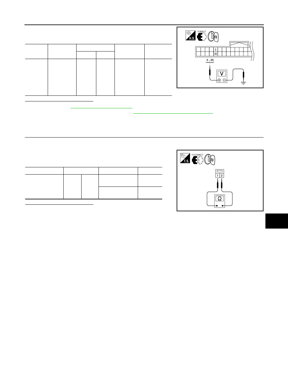
BACK DOOR REQUEST SWITCH : Component Inspection

INFOID:0000000005259910

1.

CHECK BACK DOOR REQUEST SWITCH OPERATION

1. Turn ignition switch OFF.

2. Disconnect back door request switch connector.

3. Check continuity between back door request switch terminals 1

and 2.

Is the inspection result normal?

YES

>> Inspection End.

NO

>> Replace back door request switch.

Connector

Item

Terminals

Condition

Voltage (V)

(Approx.)

(+)

(–)

M164

back door re-
quest switch

29

Ground

Back door re-

quest switch is 

pressed

Back door re-

quest switch is 

released

0

5

WIIA1183E

Component

Terminals

Condition

Continuity

Back door request 
switch

1

2

Back door request 
switch is pressed

Yes

Back door request 
switch is released

No

WIIA1186E

2010 Pathfinder

DLK-76

< COMPONENT DIAGNOSIS >

[WITH INTELLIGENT KEY SYSTEM]

DOOR LOCK ACTUATOR

DOOR LOCK ACTUATOR

DRIVER SIDE
DRIVER SIDE : Description

INFOID:0000000005259911

Locks/unlocks the door with the signal from BCM.

DRIVER SIDE : Component Function Check

INFOID:0000000005259912

1.

CHECK FUNCTION

1. Use CONSULT-III to perform Active Test "DOOR LOCK".

2. Touch “ALL LOCK” or “ALL UNLOCK” to check that it works normally.
Is the inspection result normal?

YES

>> Door lock actuator is OK.

NO

>> Refer to 

DLK-76, "DRIVER SIDE : Diagnosis Procedure"

.

DRIVER SIDE : Diagnosis Procedure

INFOID:0000000005259913

Regarding Wiring Diagram information, refer to 

DLK-131, "Wiring Diagram — POWER DOOR LOCK SYS-

TEM —"

.

1.

CHECK DOOR LOCK ACTUATOR SIGNAL

1. Turn ignition switch OFF.

2. Check voltage between BCM connector M20 terminals 59, 65

and ground.

Is the inspection result normal?

YES

>> GO TO 2

NO

>> GO TO 3

2.

CHECK DOOR LOCK ACTUATOR HARNESS

1. Disconnect BCM and front door lock assembly LH (actuator).

2. Check continuity between BCM connector (A) M20 terminals 59,

65 and front door lock assembly LH (actuator) connector (B)

D14 terminals 1, 2. 

Is the inspection result normal?

YES

>> Replace front door lock assembly LH (actuator).

Connector

Terminals

Condition

Voltage (V)

(Approx.)

(+)

(-)

M20

59

Ground

Driver door lock/unlock 
switch is turned to UN-
LOCK

 Battery voltage

65

Driver door lock/unlock 
switch is turned to LOCK

 Battery voltage

LIIA1046E

Connector

Terminals

Connector

Terminals

Continuity

M20

59

D14

2

Yes

65

1

ALKIA1191ZZ

2010 Pathfinder

DOOR LOCK ACTUATOR

DLK-77

< COMPONENT DIAGNOSIS >

[WITH INTELLIGENT KEY SYSTEM]

C

D

E

F

G

H

I

J

L

M

A

B

DLK

N

O

P

NO

>> Repair or replace harness.

3.

CHECK DOOR LOCK ACTUATOR HARNESS

1. Disconnect BCM and front door lock assembly LH (actuator).

2. Check continuity between BCM connector M20 terminals 59, 65

and ground.

Is the inspection result normal?

YES

>> Replace BCM. Refer to 

BCS-59, "Removal and Installation"

.

NO

>> Repair or replace harness.

PASSENGER SIDE
PASSENGER SIDE : Description

INFOID:0000000005259914

Locks/unlocks the door with the signal from BCM.

PASSENGER SIDE : Component Function Check

INFOID:0000000005259915

1.

CHECK FUNCTION

1. Use CONSULT-III to perform Active Test DOOR LOCK.

2. Touch “ALL LOCK” or “ALL UNLOCK” to check that it works normally.
Is the inspection result normal?

YES

>> Door lock actuator is OK.

NO

>> Refer to 

DLK-77, "PASSENGER SIDE : Diagnosis Procedure"

.

PASSENGER SIDE : Diagnosis Procedure

INFOID:0000000005259916

Regarding Wiring Diagram information, refer to 

DLK-131, "Wiring Diagram — POWER DOOR LOCK SYS-

TEM —"

.

1.

CHECK FRONT DOOR LOCK ACTUATOR RH SIGNAL

1. Turn ignition switch OFF.

2. Check voltage between BCM connector M20 terminals 65, 66

and ground.

Is the inspection result normal?

YES

>> GO TO 2

Connector

Terminals

Continuity

M20

59

Ground

No

65

ALKIA0633ZZ

Connector

Terminals

Condition

Voltage (V)

(Approx.)

(+)

(-)

M20

65

Ground

Door lock/unlock switch is 
turned to LOCK

 Battery voltage 

for 300 ms

66

Door lock/unlock switch is 
turned to UNLOCK

LIIA1048E

2010 Pathfinder

DLK-78

< COMPONENT DIAGNOSIS >

[WITH INTELLIGENT KEY SYSTEM]

DOOR LOCK ACTUATOR

NO

>> GO TO 3

2.

CHECK DOOR LOCK ACTUATOR HARNESS

1. Disconnect BCM and front door lock actuator RH.

2. Check continuity between BCM connector (A) M20 terminals 65,

66 and front door lock actuator RH (B) D114 terminals 1, 2.

Is the inspection result normal?

YES

>> Replace front door lock actuator RH. Refer to 

DLK-199, "Removal and Installation"

.

NO

>> Repair or replace harness.

3.

CHECK DOOR LOCK ACTUATOR HARNESS

1. Disconnect BCM and front door lock actuator RH.

2. Check continuity between BCM connector M19 terminals 65, 66

and ground.

Is the inspection result normal?

YES

>> Replace BCM. Refer to 

BCS-59, "Removal and Installation"

.

NO

>> Repair or replace harness.

REAR LH
REAR LH : Description

INFOID:0000000005259917

Locks/unlocks the door with the signal from BCM.

REAR LH : Component Function Check

INFOID:0000000005259918

1.

CHECK FUNCTION

1. Use CONSULT-III to perform Active Test "DOOR LOCK".

2. Touch “ALL LOCK” or “ALL UNLOCK” to check that it works normally.
Is the inspection result normal?

YES

>> Door lock actuator is OK.

NO

>> Refer to 

DLK-78, "REAR LH : Diagnosis Procedure"

.

REAR LH : Diagnosis Procedure

INFOID:0000000005259919

Regarding Wiring Diagram information, refer to 

DLK-131, "Wiring Diagram — POWER DOOR LOCK SYS-

TEM —"

.

Terminal

Continuity

65

2

Yes

66

1

ALKIA1192ZZ

Terminals

Continuity

65

Ground

No

66

ALKIA0631ZZ

2010 Pathfinder

DOOR LOCK ACTUATOR

DLK-79

< COMPONENT DIAGNOSIS >

[WITH INTELLIGENT KEY SYSTEM]

C

D

E

F

G

H

I

J

L

M

A

B

DLK

N

O

P

1.

CHECK DOOR LOCK ACTUATOR SIGNAL

1. Turn ignition switch OFF.

2. Check voltage between BCM connector M20 terminals 65, 66

and ground.

Is the inspection result normal?

YES

>> GO TO 2

NO

>> GO TO 3

2.

CHECK DOOR LOCK ACTUATOR HARNESS

NOTE:

The passenger select unlock relay must remain connected during this test. 

1. Disconnect BCM and rear door lock actuator LH.

2. Check continuity between BCM connector (A) M20 terminals 65,

66 and rear door lock actuator LH connector (B) D205 terminals

1, 2.

Is the inspection result normal?

YES

>> Replace rear door lock actuator LH.

NO

>> Repair or replace harness or passenger select unlock relay.

3.

CHECK DOOR LOCK ACTUATOR HARNESS

1. Disconnect BCM and each door lock actuator.

2. Check continuity between BCM connector M20 terminals 65, 66

and ground.

Is the inspection result normal?

YES

>> Replace BCM. Refer to 

BCS-59, "Removal and Installation"

.

NO

>> Repair or replace harness or passenger select unlock relay.

REAR RH

Connector

Terminals

Condition

Voltage (V)

(Approx.)

(+)

(-)

M20

65

Ground

Door lock/unlock switch 
is turned to LOCK

 Battery voltage 

for 300 ms

66

Door lock/unlock switch 
is turned to UNLOCK

LIIA1048E

Terminals

Continuity

65

2

Yes

66

1

ALKIA1192ZZ

Terminals

Continuity

65

Ground

No

66

No

ALKIA0631ZZ

2010 Pathfinder

DLK-80

< COMPONENT DIAGNOSIS >

[WITH INTELLIGENT KEY SYSTEM]

DOOR LOCK ACTUATOR

REAR RH : Description

INFOID:0000000005259920

Locks/unlocks the door with the signal from BCM.

REAR RH : Component Function Check

INFOID:0000000005259921

1.

CHECK FUNCTION

1. Use CONSULT-III to perform Active Test "DOOR LOCK".

2. Touch “ALL LOCK” or “ALL UNLOCK” to check that it works normally.
Is the inspection result normal?

YES

>> Door lock actuator is OK.

NO

>> Refer to 

DLK-80, "REAR RH : Diagnosis Procedure"

.

REAR RH : Diagnosis Procedure

INFOID:0000000005259922

Regarding Wiring Diagram information, refer to 

DLK-131, "Wiring Diagram — POWER DOOR LOCK SYS-

TEM —"

.

1.

CHECK DOOR LOCK ACTUATOR SIGNAL

1. Turn ignition switch OFF.

2. Check voltage between BCM connector M20 terminals 65, 66

and ground.

Is the inspection result normal?

YES

>> GO TO 2

NO

>> GO TO 3

2.

CHECK DOOR LOCK ACTUATOR HARNESS

NOTE:

The passenger select unlock relay must remain connected during this test. 

1. Disconnect BCM and rear door lock actuator RH.

2. Check continuity between BCM connector (A) M20 terminals 65,

66 and rear door lock actuator RH connector (B) D305 terminals

1, 2. 

Is the inspection result normal?

YES

>> Replace rear door lock actuator RH.

NO

>> Repair or replace harness or passenger select unlock relay.

Connector

Terminals

Condition

Voltage (V)

(Approx.)

(+)

(-)

M20

65

Ground

Door lock/unlock switch 
is turned to LOCK

 Battery voltage 

for 300 ms

66

Door lock/unlock switch 
is turned to UNLOCK

LIIA1048E

Terminals

Continuity

65

2

Yes

66

1

ALKIA1192ZZ

2010 Pathfinder

DOOR LOCK ACTUATOR

DLK-81

< COMPONENT DIAGNOSIS >

[WITH INTELLIGENT KEY SYSTEM]

C

D

E

F

G

H

I

J

L

M

A

B

DLK

N

O

P

3.

CHECK DOOR LOCK ACTUATOR HARNESS

1. Disconnect BCM and rear door lock actuator RH.

2. Check continuity between BCM connector (A) M20 terminals 65,

66 and ground. 

Is the inspection result normal?

YES

>> Replace BCM. Refer to 

BCS-59, "Removal and Installation"

.

NO

>> Repair or replace harness or passenger select unlock relay.

BACK DOOR LATCH
BACK DOOR LATCH : Description

INFOID:0000000005259923

Locks/unlocks the door with the signal from BCM.

BACK DOOR LATCH : Diagnosis Procedure

INFOID:0000000005259924

Regarding Wiring Diagram information, refer to 

DLK-131, "Wiring Diagram — POWER DOOR LOCK SYS-

TEM —"

.

1.

CHECK BACK DOOR LATCH SIGNAL

NOTE:

Ensure back door opener switch is operating properly before proceeding.

1. Turn ignition switch OFF.

2. Unlock all doors using main power window and door lock/unlock switch.

3. While pressing the back door opener switch, check voltage

between BCM connector M19 terminal 53 and ground.

Is the inspection result normal?

YES

>> GO TO 2

NO

>> GO TO 4

2.

CHECK BACK DOOR LATCH HARNESS FOR OPEN

1. Disconnect BCM and back door latch.

Terminals

Continuity

65

Ground

No

66

ALKIA0631ZZ

Connector

Terminals

Condition

Voltage (V)

(Approx.)

(+)

(-)

M19

53

Ground

Back door opener switch 
is pressed

 Battery voltage 

for 300 ms

ALKIA1704ZZ

2010 Pathfinder

DLK-82

< COMPONENT DIAGNOSIS >

[WITH INTELLIGENT KEY SYSTEM]

DOOR LOCK ACTUATOR

2. Check continuity between BCM connector (A) M19 terminals 53

and back door latch connector (B) D502 terminal 1.

Is the inspection result normal?

YES

>> GO TO 3

NO

>> Repair or replace harness.

3.

CHECK BACK DOOR LATCH GROUND

Check continuity between back door latch connector D502 terminal

2 and ground.

Is the inspection result normal?

YES

>> Replace back door latch.

NO

>> Repair or replace harness.

4.

CHECK BACK DOOR LATCH HARNESS FOR SHORT

1. Disconnect BCM and back door latch.

2. Check continuity between BCM connector M19 terminal 53 and

ground.

Is the inspection result normal?

YES

>> Replace BCM. Refer to 

BCS-59, "Removal and Installation"

.

NO

>> Repair or replace harness.

Terminals

Continuity

53

1

Yes

ALKIA1705ZZ

Terminals

Continuity

2

Ground

Yes

ALKIA1712ZZ

Terminals

Continuity

53

Ground

No

ALKIA1706ZZ

2010 Pathfinder


Content      ..     145      146      147      148     ..