Nissan Pathfinder (2010 year). Manual - part 125


  Index      Manuals     Nissan Pathfinder (2010 year) - Service and Repair Manual


Search            copyright infringement  


Content      ..     123      124      125      126     ..


Nissan Pathfinder (2010 year). Manual - part 125


CHG-22

< ON-VEHICLE REPAIR >

GENERATOR

• For this model, the power generation variable voltage control system that controls the power generation volt-

age of the generator has been adopted. Therefore, the power generation variable voltage control system

inspection should be performed after replacing the generator in order to ensure that the system operates

normally. 

VK56DE MODELS

Removal

1. Disconnect the negative battery terminal. Refer to 

PG-78, "Removal and Installation"

.

2. Drain the engine coolant. Refer to 

CO-40, "Changing Engine Coolant"

.

3. Remove air duct and resonator assembly and air cleaner case (upper). Refer to 

EM-161, "Exploded

View"

.

4. Disconnect the lower radiator hose and the transmission oil cooler hoses from the radiator. Refer to 

CO-

44, "Exploded View"

.

5. Remove the lower fan shroud. Refer to 

CO-44, "Exploded View"

.

6. Disconnect the upper radiator hose and the coolant reservoir hose from the radiator. Refer to 

CO-44,

"Exploded View"

.

7. Remove the upper fan shroud. Refer to 

CO-44, "Exploded View"

.

8. Remove the drive belt. Refer to 

EM-149, "Removal and Installation"

.

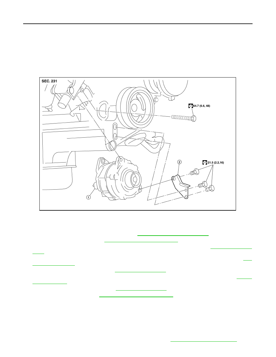
9. Remove the lower bracket, using power tools. 
10. Remove the generator upper bolt, using power tools.
11. Disconnect the generator harness connectors.
12. Remove the generator.

Installation

Installation is in the reverse order of removal.

• Install the generator and check the tension of the drive belt. Refer to 

EM-149, "Checking Drive Belts"

.

Terminal nut

: 10.8 N·m (1.1 kg-m, 8 ft-lb)

1.

Generator

2.

Lower bracket

AWBIA0701GB

2010 Pathfinder

CHG

GENERATOR

CHG-23

< ON-VEHICLE REPAIR >

C

D

E

F

G

H

I

J

K

L

B

A

O

P

N

CAUTION:

Tighten terminal nut carefully.

• For this model, the power generation variable voltage control system that controls the power generation volt-

age of the generator has been adopted. Therefore, the power generation variable voltage control system

inspection should be performed after replacing the generator in order to ensure that the system operates

normally. 

Terminal nut

: 10.8 N·m (1.1 kg-m, 8 ft-lb)

2010 Pathfinder

CHG-24

< SERVICE DATA AND SPECIFICATIONS (SDS) 

SERVICE DATA AND SPECIFICATIONS (SDS)

SERVICE DATA AND SPECIFICATIONS (SDS)

SERVICE DATA AND SPECIFICATIONS (SDS)

Generator

INFOID:0000000005255222

*: Always check with the Parts Department for the latest parts information

Type*

TG15S147

Valeo

Engine

VQ40DE/VK56DE

Nominal rating

14V-130A

Ground polarity

Negative

Minimum revolution under no-load

1,200 rpm

Hot output current (When 13.5 volts is applied)

More than 52A/1,500 rpm
More than 82A/1,800 rpm

More than 115A/2,500 rpm

More than 130A/5,000 rpm

Regulated output voltage

13.5V @ 5,000 rpm @ 20

°

C (68

°

F)

Adjustment range of power generation variable 
voltage control 

11.4 - 15.6V

2010 Pathfinder

CO-1

ENGINE

C

D

E

F

G

H

I

J

K

L

M

SECTION 

CO

A

CO

N

O

P

CONTENTS

ENGINE COOLING SYSTEM

VQ40DE

PRECAUTION ...............................................

3

PRECAUTIONS ...................................................

3

Precaution for Supplemental Restraint System 
(SRS) "AIR BAG" and "SEAT BELT PRE-TEN-
SIONER" .................................................................
..

3

Precaution Necessary for Steering Wheel Rota-
tion After Battery Disconnect ...................................
..

3

Precaution for Liquid Gasket .....................................

4

PREPARATION ............................................

5

PREPARATION ...................................................

5

Special Service Tool  .................................................

5

Commercial Service Tool  ..........................................

5

FUNCTION DIAGNOSIS ...............................

7

COOLING SYSTEM ............................................

7

Cooling Circuit ...........................................................

7

Schematic .................................................................

8

OVERHEATING CAUSE ANALYSIS ..................

9

Troubleshooting Chart ...............................................

9

ON-VEHICLE MAINTENANCE ....................

11

ENGINE COOLANT  ...........................................

11

System Inspection ...................................................

11

Changing Engine Coolant  .......................................

12

ON-VEHICLE REPAIR .................................

16

RADIATOR .........................................................

16

Exploded View  ........................................................

16

Removal and Installation .........................................

16

Checking Radiator ...................................................

18

ENGINE COOLING FAN  ....................................

19

Exploded View  ........................................................

19

Removal and Installation (Crankshaft driven type) ....

19

Removal and Installation (Motor driven type)  ..........

20

WATER PUMP  ..................................................

22

Exploded View .........................................................

22

Removal and Installation  .........................................

22

WATER INLET AND THERMOSTAT ASSEM-
BLY ....................................................................

27

Exploded View .........................................................

27

Removal and Installation  .........................................

27

WATER OUTLET AND WATER PIPING  ..........

29

Exploded View .........................................................

29

Removal and Installation  .........................................

29

SERVICE DATA AND SPECIFICATIONS 
(SDS) ............................................................

30

SERVICE DATA AND SPECIFICATIONS 
(SDS) .................................................................

30

Standard and Limit  ..................................................

30

VK56DE

PRECAUTION ..............................................

31

PRECAUTIONS .................................................

31

Precaution for Supplemental Restraint System 
(SRS) "AIR BAG" and "SEAT BELT PRE-TEN-
SIONER" .................................................................

31

Precaution Necessary for Steering Wheel Rota-
tion After Battery Disconnect  ...................................

31

Precaution for Liquid Gasket  ...................................

32

PREPARATION ...........................................

33

PREPARATION .................................................

33

Special Service Tool ................................................

33

Commercial Service Tool  ........................................

33

FUNCTION DIAGNOSIS ..............................

35

COOLING SYSTEM  ..........................................

35

2010 Pathfinder

CO-2

Cooling Circuit  ........................................................

35

Schematic ...............................................................

36

OVERHEATING CAUSE ANALYSIS  ................

37

Troubleshooting Chart  ............................................

37

ON-VEHICLE MAINTENANCE ...................

39

ENGINE COOLANT ...........................................

39

System Inspection  ..................................................

39

Changing Engine Coolant .......................................

40

ON-VEHICLE REPAIR  ................................

44

RADIATOR ........................................................

44

Exploded View ........................................................

44

Removal and Installation  ........................................

44

Checking Radiator  ..................................................

46

ENGINE COOLING FAN  ...................................

48

Exploded View  ........................................................

48

Removal and Installation (Crankshaft Driven 
Type) .......................................................................

48

Removal and Installation (Motor Driven Type) ........

49

WATER PUMP ...................................................

51

Exploded View  ........................................................

51

Removal and Installation .........................................

51

THERMOSTAT AND WATER PIPING  ..............

53

Exploded View  ........................................................

53

Removal and Installation .........................................

53

SERVICE DATA AND SPECIFICATIONS 
(SDS) ..........................................................

55

SERVICE DATA AND SPECIFICATIONS 
(SDS) .................................................................

55

Standard and Limit ..................................................

55

2010 Pathfinder

PRECAUTIONS

CO-3

< PRECAUTION >

[VQ40DE]

C

D

E

F

G

H

I

J

K

L

M

A

CO

N

P

O

PRECAUTION

PRECAUTIONS

Precaution for Supplemental Restraint System (SRS) "AIR BAG" and "SEAT BELT 
PRE-TENSIONER"

INFOID:0000000005531978

The Supplemental Restraint System such as “AIR BAG” and “SEAT BELT PRE-TENSIONER”, used along

with a front seat belt, helps to reduce the risk or severity of injury to the driver and front passenger for certain

types of collision. This system includes seat belt switch inputs and dual stage front air bag modules. The SRS

system uses the seat belt switches to determine the front air bag deployment, and may only deploy one front

air bag, depending on the severity of a collision and whether the front occupants are belted or unbelted.

Information necessary to service the system safely is included in the SR and SB section of this Service Man-

ual.

WARNING:

• To avoid rendering the SRS inoperative, which could increase the risk of personal injury or death in

the event of a collision which would result in air bag inflation, all maintenance must be performed by

an authorized NISSAN/INFINITI dealer.

• Improper maintenance, including incorrect removal and installation of the SRS, can lead to personal

injury caused by unintentional activation of the system. For removal of Spiral Cable and Air Bag

Module, see the SR section.

• Do not use electrical test equipment on any circuit related to the SRS unless instructed to in this

Service Manual. SRS wiring harnesses can be identified by yellow and/or orange harnesses or har-

ness connectors.

PRECAUTIONS WHEN USING POWER TOOLS (AIR OR ELECTRIC) AND HAMMERS

WARNING:

• When working near the Airbag Diagnosis Sensor Unit or other Airbag System sensors with the Igni-

tion ON or engine running, DO NOT use air or electric power tools or strike near the sensor(s) with a

hammer. Heavy vibration could activate the sensor(s) and deploy the air bag(s), possibly causing

serious injury.

• When using air or electric power tools or hammers, always switch the Ignition OFF, disconnect the

battery, and wait at least 3 minutes before performing any service.

Precaution Necessary for Steering Wheel Rotation After Battery Disconnect

INFOID:0000000005260549

NOTE:

• This Procedure is applied only to models with Intelligent Key system and NATS (NISSAN ANTI-THEFT SYS-

TEM).

• Remove and install all control units after disconnecting both battery cables with the ignition knob in the

LOCK

 position.

• Always use CONSULT-III to perform self-diagnosis as a part of each function inspection after finishing work.

If DTC is detected, perform trouble diagnosis according to self-diagnostic results.

For models equipped with the Intelligent Key system and NATS, an electrically controlled steering lock mech-

anism is adopted on the key cylinder.

For this reason, if the battery is disconnected or if the battery is discharged, the steering wheel will lock and

steering wheel rotation will become impossible.

If steering wheel rotation is required when battery power is interrupted, follow the procedure below before

starting the repair operation.

OPERATION PROCEDURE

1. Connect both battery cables.

NOTE:

Supply power using jumper cables if battery is discharged.

2. Use the Intelligent Key or mechanical key to turn the ignition switch to the 

ACC

 position. At this time, the

steering lock will be released.

3. Disconnect both battery cables. The steering lock will remain released and the steering wheel can be

rotated.

4. Perform the necessary repair operation.

2010 Pathfinder

CO-4

< PRECAUTION >

[VQ40DE]

PRECAUTIONS

5. When the repair work is completed, return the ignition switch to the 

LOCK

 position before connecting

the battery cables. (At this time, the steering lock mechanism will engage.)

6. Perform a self-diagnosis check of all control units using CONSULT-III. 

Precaution for Liquid Gasket

INFOID:0000000005260550

REMOVAL OF LIQUID GASKET SEALING

• After removing nuts and bolts, separate the mating surface and

remove old liquid gasket sealing using Tool.

CAUTION:

Be careful not to damage the mating surfaces.

• Tap seal cutter to insert it (1), and then slide it by tapping on the

side (2) as shown.

• In areas where Tool is difficult to use, use plastic hammer to lightly

tap the part, to remove it.

CAUTION:

If for some unavoidable reason tool such as screwdriver is

used, be careful not to damage the mating surfaces.

LIQUID GASKET APPLICATION PROCEDURE

1. Remove the old liquid gasket adhering to the gasket application

surface and the mating surface using suitable tool.

• Remove liquid gasket completely from the groove of the gas-

ket application surface, bolts, and bolt holes.

2. Thoroughly clean the mating surfaces and remove adhering

moisture, grease and foreign materials.

3. Attach liquid gasket tube to the Tool.

Use Genuine RTV Silicone Sealant or equivalent. Refer to

GI-14, "Recommended Chemical Products and Sealants"

.

4. Apply the liquid gasket without breaks to the specified location

with the specified dimensions.

• If there is a groove for the liquid gasket application, apply the

liquid gasket to the groove.

• As for bolt holes, normally apply the liquid gasket inside the

holes. Occasionally, it should be applied outside the holes.

Make sure to read the text of this manual.

• Within five minutes of liquid gasket application, install the mat-

ing component.

• If the liquid gasket protrudes, wipe it off immediately.

• Do not retighten nuts or bolts after the installation.

• Wait 30 minutes or more after installation, before refilling the

engine with engine oil and engine coolant.

CAUTION:

If there are specific instructions in this manual, observe them.

Tool number

: KV10111100 (J-37228)

WBIA0566E

PBIC0003E

Tool number

: WS39930000 (

)

WBIA0567E

SEM159F

2010 Pathfinder

PREPARATION

CO-5

< PREPARATION >

[VQ40DE]

C

D

E

F

G

H

I

J

K

L

M

A

CO

N

P

O

PREPARATION

PREPARATION

Special Service Tool

INFOID:0000000005260551

The actual shapes of Kent-Moore tools may differ from those of special service tools illustrated here.

Commercial Service Tool

INFOID:0000000005260552

Tool number
(Kent-Moore No.)
Tool name

Description

KV10111100
(J-37228)
Seal cutter

Removing chain tensioner cover and water 
pump cover

WS39930000
( — )
Tube presser

Pressing the tube of liquid gasket

EG17650301
(J-33984-A)
Radiator cap tester adapter

Adapting radiator cap tester to radiator cap 
and radiator filler neck

a: 28 (1.10) dia.
b: 31.4 (1.236) dia.
c: 41.3 (1.626) dia.

Unit: mm (in)

KV991J0070
(J-45695)
Coolant refill tool

Filling cooling system

KV991J0010
(J-23688)
Engine coolant refractometer

Checking concentration of ethylene glycol in 
engine coolant

NT046

S-NT052

S-NT564

LMA053

WBIA0539E

2010 Pathfinder


Content      ..     123      124      125      126     ..