Nissan Pathfinder (2010 year). Manual - part 114


  Index      Manuals     Nissan Pathfinder (2010 year) - Service and Repair Manual


Search            copyright infringement  


Content      ..     112      113      114      115     ..


Nissan Pathfinder (2010 year). Manual - part 114


BRC-124

< PREPARATION >

[VDC/TCS/ABS]

PREPARATION

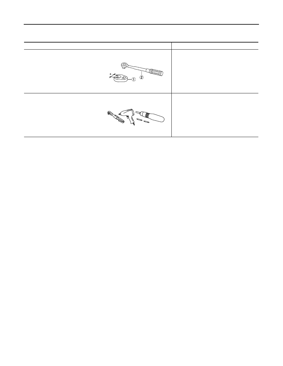
Commercial Service Tool

INFOID:0000000005258783

Tool name

Description

1. Flare nut crowfoot
2. Torque wrench

Removing and installing brake piping

a: 10 mm (0.39 in)/12 mm (0.47 in)

Power tool

Removing nuts, bolts and screws

S-NT360

PIIB1407E

2010 Pathfinder

WHEEL SENSORS

BRC-125

< REMOVAL AND INSTALLATION >

[VDC/TCS/ABS]

C

D

E

G

H

I

J

K

L

M

A

B

BRC

N

O

P

REMOVAL AND INSTALLATION

WHEEL SENSORS

Removal and Installation

INFOID:0000000005258784

REMOVAL

1. Remove the disc rotor. Refer to 

BR-40, "Removal and Installation of Brake Caliper and Disc Rotor"

 (front)

or 

BR-45, "Removal and Installation of Brake Caliper and Disc Rotor"

 (rear).

2. Remove the wheel sensor bolt.

• When removing the front wheel sensor, first remove the disc rotor to gain access to the front wheel sen-

sor bolt. Refer to 

BR-45, "Removal and Installation of Brake Caliper and Disc Rotor"

.

• When removing the rear wheel sensor, first remove the spare tire.

3. Pull the wheel sensor out, being careful to turn it as little as possible.

CAUTION:

• Be careful not to damage wheel sensor edge or the sensor rotor teeth.

• Do not pull on the wheel sensor harness.

4. Disconnect then wheel sensor harness connector, then remove the wheel sensor harness from the

mounts and remove the wheel sensor.

• When removing the rear wheel sensor, both sensors must be removed as they are on the same har-

ness.

INSTALLATION

Installation is in the reverse order of removal.

CAUTION:

• Inspect wheel sensor O-ring, replace wheel sensor if damaged.

• Before installing the wheel sensor, make sure no foreign materials (such as iron fragments) are

adhered to the pick-up part of the wheel sensor, to the inside of the wheel sensor hole or on the sen-

sor rotor in the wheel hub assembly.

• Clean wheel sensor hole and mating surface with brake cleaner and a lint-free shop rag. Be careful

that dirt and debris do not enter the axle or wheel hub assembly.

NOTE:

Apply a coat of suitable grease to the wheel sensor O-ring and mating hole.

1.

Front wheel sensor LH

2.

Rear wheel sensor RH

AWFIA0527GB

2010 Pathfinder

BRC-126

< REMOVAL AND INSTALLATION >

[VDC/TCS/ABS]

SENSOR ROTOR

SENSOR ROTOR

Removal and Installation

INFOID:0000000005258785

FRONT WHEEL SENSOR ROTOR

The front wheel sensor rotors are built into the front wheel hub and bearing assemblies and are not remov-

able. If damaged, replace the front wheel hub and bearing assembly. Refer to 

FAX-10, "Removal and Installa-

tion"

.

REAR WHEEL SENSOR ROTOR

Removal

1. Remove the side flange from the final drive assembly. Refer to 

DLN-419, "Removal and Installation"

(R200) or 

DLN-457, "Removal and Installation"

 (R230).

CAUTION:

Discard side oil seal.

2. Using suitable tool with Tool (puller), remove the sensor rotor from the side flange.

Installation

1. Install the new sensor rotor on the side flange using Tools and a

suitable press as shown. Make sure the sensor rotor is fully

seated on the side flange.

CAUTION:

Do not reuse the old sensor rotor.

2. Install the side flange on the final drive assembly. Refer to 

DLN-419, "Removal and Installation"

 (R200) or

DLN-457, "Removal and Installation"

 (R230).

CAUTION:

Do not reuse the side oil seal. The side oil seal must be replaced every time the side flange is

removed from the final drive assembly.

Tool number

: ST30031000 ( — )

Tool numbers

A: ST30720000 (J-25405)
B: ST27863000 ( — )
C: KV40104710 ( — )

WFIA0334E

2010 Pathfinder

ACTUATOR AND ELECTRIC UNIT (ASSEMBLY)

BRC-127

< REMOVAL AND INSTALLATION >

[VDC/TCS/ABS]

C

D

E

G

H

I

J

K

L

M

A

B

BRC

N

O

P

ACTUATOR AND ELECTRIC UNIT (ASSEMBLY)

Removal and Installation

INFOID:0000000005258786

VQ40DE

ALFIA0146ZZ

1.

From master cylinder secondary side
18.2 N·m (1.9 kg-m, 13 ft-lb)

2.

To rear right disc brake
13.0 N·m (1.3 kg-m, 10 ft-lb)

3.

To rear left disc brake
13.0 N·m (1.3 kg-m, 10 ft-lb)

4.

To front right disc brake
13.0 N·m (1.3 kg-m, 10 ft-lb)

5.

To front left disc brake
13.0 N·m (1.3 kg-m, 10 ft-lb)

6.

From master cylinder primary side
18.2 N·m (1.9 kg-m, 13 ft-lb)

7.

ABS actuator and electric unit (control 
unit)

8.

Harness connector

Front

2010 Pathfinder

BRC-128

< REMOVAL AND INSTALLATION >

[VDC/TCS/ABS]

ACTUATOR AND ELECTRIC UNIT (ASSEMBLY)

VK56DE

REMOVAL

1. Disconnect the battery negative terminal.
2. Drain the brake fluid. Refer to 

BR-20, "Drain and Refill"

.

3. Remove air cleaner assembly. Refer to 

EM-26, "Removal and Installation"

 (VQ40) or 

EM-161, "Removal

and Installation"

 (VK56).

4. Disconnect the actuator harness from the ABS actuator and electric unit (control unit).

CAUTION:

• To remove the brake tubes, use a flare nut wrench to prevent the flare nuts and brake tubes from

being damaged.

• Be careful not to splash brake fluid on painted areas.

5. Disconnect the brake tubes.
6. Remove the three bolts and remove the ABS actuator and electric unit (control unit) and bracket.
7. Remove the bracket from the ABS actuator and electric unit (control unit).

INSTALLATION

Installation is in the reverse order of removal.

• If the ABS actuator and electric unit (control unit) is replaced, the neutral position of the steering angle sen-

sor position must be reset. Refer to 

BRC-9, "CALIBRATION OF DECEL G SENSOR : Special Repair

Requirement"

.

CAUTION:

AWFIA0593GB

1.

To rear left disc brake
13.0 N·m (1.3 kg-m, 10 ft-lb)

2.

To rear right disc brake
13.0 N·m (1.3 kg-m, 10 ft-lb)

3.

To front left disc brake
13.0 N·m (1.3 kg-m, 10 ft-lb)

4.

To front right disc brake
13.0 N·m (1.3 kg-m, 10 ft-lb)

5.

From master cylinder secondary side
18.2 N·m (1.9 kg-m, 13 ft-lb)

6.

From master cylinder primary side
18.2 N·m (1.9 kg-m, 13 ft-lb)

7.

ABS actuator and electric unit 
(control unit)

8.

Harness connector

9.

Grommet

10. Collar

Front

2010 Pathfinder

ACTUATOR AND ELECTRIC UNIT (ASSEMBLY)

BRC-129

< REMOVAL AND INSTALLATION >

[VDC/TCS/ABS]

C

D

E

G

H

I

J

K

L

M

A

B

BRC

N

O

P

• To tighten the brake tube flare nuts use a suitable tool (flare nut wrench).

• Always tighten the brake tube flare nuts to specification when installing.

• Never reuse the drained brake fluid.

• After installation of the ABS actuator and electric unit (control unit), refill the brake system with new

brake fluid. Then bleed the air from the brake system. Refer to 

BR-20, "Bleeding Brake System"

.

• If the ABS actuator and electronic unit (control unit) is replaced, the neutral position of the steering

angle sensor must be reset. Refer to 

BRC-9, "CALIBRATION OF DECEL G SENSOR : Special Repair

Requirement"

.

2010 Pathfinder

BRC-130

< REMOVAL AND INSTALLATION >

[VDC/TCS/ABS]

STEERING ANGLE SENSOR

STEERING ANGLE SENSOR

Removal and Installation

INFOID:0000000005258787

REMOVAL

1. Remove the spiral cable. Refer to 

SR-7, "Removal and Installation"

.

2. Remove the screws and remove the steering angle sensor from the spiral cable.

INSTALLATION

Installation is in the reverse order of removal.

• Reset the neutral position of the steering angle sensor. Refer to 

BRC-9, "CALIBRATION OF DECEL G SEN-

SOR : Special Repair Requirement"

.

CAUTION:

Any time the steering angle sensor is removed and installed or replaced, you must reset the neutral

position of the steering angle sensor. Refer to 

BRC-9, "CALIBRATION OF DECEL G SENSOR : Special

Repair Requirement"

.

2010 Pathfinder

G SENSOR

BRC-131

< REMOVAL AND INSTALLATION >

[VDC/TCS/ABS]

C

D

E

G

H

I

J

K

L

M

A

B

BRC

N

O

P

G SENSOR

Removal and Installation

INFOID:0000000005258788

REMOVAL

1. Remove the center console. Refer to 

IP-18, "Exploded View"

.

2. Remove the yaw rate/side/decel G sensor nuts as shown.

CAUTION:

• Do not use power tools to remove or install the yaw rate/

side/decel G sensor.

• Do not drop or strike the yaw rate/side/decel G sensor.

NOTE:

The location of the yaw rate/side/decel G sensor is the same for

all models.

3. Disconnect the yaw rate/side/decel G sensor connector and remove the yaw rate/side/decel G sensor.

INSTALLATION

Installation is in the reverse order of removal.

• After installing the yaw rate/side/decel G sensor, it is necessary to calibrate the yaw rate/side/decel G sen-

sor. Refer to 

BRC-9, "CALIBRATION OF DECEL G SENSOR : Special Repair Requirement"

.

WFIA0230E

2010 Pathfinder


Content      ..     112      113      114      115     ..