Nissan Pathfinder (2010 year). Manual - part 52


  Index      Manuals     Nissan Pathfinder (2010 year) - Service and Repair Manual


Search            copyright infringement  


Content      ..     50      51      52      53     ..


Nissan Pathfinder (2010 year). Manual - part 52


AV

REAR TWEETER

AV-223

< COMPONENT DIAGNOSIS >

[BOSE AUDIO WITHOUT NAVIGATION]

C

D

E

F

G

H

I

J

K

L

M

B

A

O

P

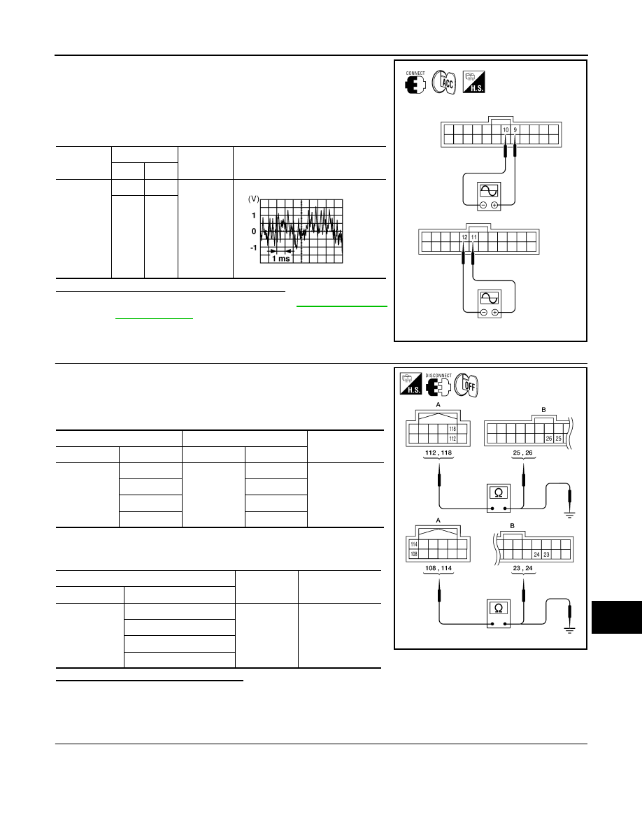
1. Connect BOSE speaker amp. connectors and suspect tweeter

connector.

2. Turn ignition switch to ACC.

3. Push “POWER” switch.

4. Check the signal between BOSE speaker amp. harness connec-

tors B75 terminals with CONSULT-III or oscilloscope.

Are audio signal voltage readings as specified?

YES

>> Replace suspect tweeter. Refer to 

AV-294, "Removal

and Installation"

.

NO

>> GO TO 3

3.

HARNESS CHECK

1. Disconnect AV control unit connector M69 and BOSE speaker

amp. connector B75.

2. Check continuity between AV control unit harness connector

M69 (A) and BOSE speaker amp. harness connector B75 (B).

3. Check continuity between AV control unit harness connector

M69 (A) and ground.

Are the continuity results as specified?

YES

>> GO TO 4

NO

>> • Check connector housings for disconnected or loose terminals.

• Repair harness or connector.

4.

REAR TWEETER SIGNAL CHECK

Connector

Terminals

Condition

Reference

signal

(+)

(-)

B75

9

10

Receive 
audio sig-
nal

11

12

ALNIA0534GB

SKIA0177E

A

Continuity

Connector

Terminal

Connector

Terminal

M69

112

B75

26

Yes

118

25

108

24

114

23

A

Continuity

Connector

Terminal

M69

112

Ground

No

118

108

114

ALNIA0535GB

2010 Pathfinder

2010 Pathfinder

AV-224

< COMPONENT DIAGNOSIS >

[BOSE AUDIO WITHOUT NAVIGATION]

REAR TWEETER

1. Connect AV control unit connector M69 and BOSE speaker

amp. connector B75.

2. Turn ignition switch to ACC.

3. Push “POWER” switch.

4. Check the signal between AV control unit harness connector

M69 terminals with CONSULT-III or oscilloscope.

Is the audio signal voltage reading as specified?

YES

>> Replace BOSE speaker amp. Refer to 

AV-299,

"Removal and Installation"

.

NO

>> Replace AV control unit. Refer to 

AV-289, "Removal and

Installation"

.

Connector

Terminals

Condition

Reference

signal

(+)

(-)

M69

112

118

Receive 
audio sig-
nal

108

114

ALNIA0356GB

SKIA0177E

2010 Pathfinder

2010 Pathfinder

AV

SUBWOOFER

AV-225

< COMPONENT DIAGNOSIS >

[BOSE AUDIO WITHOUT NAVIGATION]

C

D

E

F

G

H

I

J

K

L

M

B

A

O

P

SUBWOOFER

Description

INFOID:0000000005259449

The AV control unit sends audio signals to the BOSE speaker amp. The BOSE speaker amp. amplifies the

audio signals before sending them to the subwoofer using the audio signal circuits.

Diagnosis Procedure

INFOID:0000000005259450

Regarding Wiring Diagram information, refer to 

AV-245, "Wiring Diagram"

.

1.

VERIFY SUBWOOFER POWER AND GROUND SUPPLY

Check power and ground supply to the subwoofer.  Refer to 

AV-197, "SUBWOOFER : Diagnosis Procedure"

Did the power and ground supply check OK?

YES

>> GO TO 2

NO

>> • Check connector housings for disconnected or loose terminals.

• Repair harness or connector.

2.

HARNESS CHECK

1. Disconnect BOSE speaker amp. connectors and subwoofer

connector.

2. Check continuity between BOSE speaker amp. harness connec-

tors B74 (A) and B75 (B) and subwoofer harness connector B72

(C).

3. Check continuity between BOSE speaker amp. harness connec-

tor B74 (A) and B75 (B) and ground.

Are the continuity results as specified?

YES

>> GO TO 3

NO

>> • Check connector housings for disconnected or loose

terminals.

• Repair harness or connector.

3.

SUBWOOFER AMP ON SIGNAL CHECK

Connector

Terminal

Connector

Terminal

Continuity

A: B74

3

C: B72

1

Yes

19

2

B: B75

22

4

Connector

Terminal

-

Continuity

A: B74

3

Ground

No

19

B: B75

22

ALNIA0536GB

2010 Pathfinder

2010 Pathfinder

AV-226

< COMPONENT DIAGNOSIS >

[BOSE AUDIO WITHOUT NAVIGATION]

SUBWOOFER

1. Connect BOSE speaker amp. connector B74.

2. Turn ignition switch to ACC.

3. Push "POWER" switch. 

4. Check voltage between subwoofer connector B72 terminal 4

and ground.

Are the voltage readings as specified?

YES

>> GO TO 4

NO

>> Replace BOSE speaker amp.  Refer to 

AV-299, "Removal and Installation"

.

4.

SUBWOOFER AUDIO SIGNAL CHECK

1. Connect BOSE speaker amp. connectors and subwoofer connector.

2. Turn ignition switch to ACC.

3. Push “POWER” switch.

4. Check the signal between BOSE speaker amp. harness connec-

tor B74 terminals with CONSULT-III or oscilloscope.

Is the audio signal voltage as specified?

YES

>> Replace subwoofer. Refer to 

AV-300, "Removal and Installation"

.

NO

>> GO TO 5

5.

HARNESS CHECK

1. Turn ignition switch OFF.

(+)

(-)

Voltage

Connector

Terminal

B72

4

Ground

Battery voltage

ALNIA0540GB

Connector

Terminals

Condition

Reference

signal

(+)

(-)

B74

19

3

Receive au-
dio signal

ALNIA0879GB

SKIA0177E

2010 Pathfinder

2010 Pathfinder

AV

SUBWOOFER

AV-227

< COMPONENT DIAGNOSIS >

[BOSE AUDIO WITHOUT NAVIGATION]

C

D

E

F

G

H

I

J

K

L

M

B

A

O

P

2. Disconnect AV control unit connector M69 and BOSE speaker

amp. connector B75.

3. Check continuity between AV control unit harness connector

M69 (A) and BOSE speaker amp. harness connector B75 (B).

4. Check continuity between AV control unit harness connector

M69 (A) and ground.

Are the continuity results as specified?

YES

>> GO TO 6

NO

>> • Check connector housings for disconnected or loose terminals.

• Repair harness or connector.

6.

BACK DOOR SPEAKER SIGNAL CHECK

1. Connect AV control unit connector M69 and BOSE speaker

amp. connector B75.

2. Turn ignition switch to ACC.

3. Push “POWER” switch.

4. Check the signal between AV control unit harness connector

M69 terminals with CONSULT-III or oscilloscope.

Is the audio signal voltage reading as specified?

YES

>> Replace BOSE speaker amp. Refer to 

AV-299,

"Removal and Installation"

.

NO

>> Replace AV control unit. Refer to 

AV-289, "Removal and

Installation"

.

A

Continuity

Connector

Terminal

Connector

Terminal

M69

112

B75

26

Yes

118

25

108

24

114

23

A

Continuity

Connector

Terminal

M69

112

Ground

No

118

108

114

ALNIA0538GB

Connector

Terminals

Condition

Reference

signal

(+)

(-)

M69

112

118

Receive 
audio sig-
nal

108

114

ALNIA0356GB

SKIA0177E

2010 Pathfinder

2010 Pathfinder

AV-228

< COMPONENT DIAGNOSIS >

[BOSE AUDIO WITHOUT NAVIGATION]

AMP ON SIGNAL CIRCUIT

AMP ON SIGNAL CIRCUIT

Description

INFOID:0000000005259451

When the audio system is turned on, a voltage signal is supplied from the AV control unit to the BOSE speaker

amp. When this signal is received, the BOSE speaker amp. will turn on.

Diagnosis Procedure

INFOID:0000000005259452

Regarding Wiring Diagram information, refer to 

AV-245, "Wiring Diagram"

.

1.

CHECK AMP ON SIGNAL (BOSE SPEAKER AMP)

1. Turn audio system ON.

2. Check voltage between BOSE speaker amp. harness connector

B75 terminal 31 and ground.

Is battery voltage present?

YES

>> Inspection End.

NO

>> GO TO 2

2.

CHECK AMP ON SIGNAL (AV CONTROL UNIT)

Check voltage between AV control unit harness connector M69 ter-

minal 110 and ground.

Is battery voltage present?

YES

>> Repair harness or connector.

NO

>> Replace AV control unit. Refer to 

AV-289, "Removal and

Installation"

.

(+)

(-)

Value (Approx.)

Connector

Terminal

B75

31

Ground

Battery Voltage

ALNIA0539GB

(+)

(-)

Value (Approx.)

Connector

Terminal

M69

110

Ground

Battery Voltage

ALNIA0370GB

2010 Pathfinder

2010 Pathfinder

AV

STEERING SWITCH

AV-229

< COMPONENT DIAGNOSIS >

[BOSE AUDIO WITHOUT NAVIGATION]

C

D

E

F

G

H

I

J

K

L

M

B

A

O

P

STEERING SWITCH

Description

INFOID:0000000005259453

When one of the steering wheel AV control switches is pushed, the resistance in the steering wheel AV control

switch circuit changes depending on which button is pushed.

Diagnosis Procedure

INFOID:0000000005259454

Regarding Wiring Diagram information, refer to 

AV-245, "Wiring Diagram"

.

1.

CHECK STEERING WHEEL AUDIO CONTROL SWITCH RESISTANCE

1. Turn ignition switch OFF.

2. Disconnect steering wheel audio control switch connector M102.

3. Check resistance between steering switch connector terminals.

Do the steering wheel audio control switches check OK?

YES

>> GO TO 2

NO

>> Replace steering wheel audio control switch. Refer to 

AV-295, "Removal and Installation"

.

2.

CHECK HARNESS

1. Disconnect AV control unit connector M42 and spiral cable con-

nector M30.

2. Check continuity between AV control unit harness connector

M42 (A) and spiral cable harness connector M30 (B).

3. Check continuity between AV control unit connector M42 (A) and ground.

Are the continuity results as specified?

YES

>> GO TO 3

Terminal

Signal name

Condition

Resistance 

(

)

(Approx.)

16

17

Seek (down)

Depress  

switch.

165

Volume (down)

Depress VOL down switch.

487

Mode

Depress MODE switch.

0

20

17

Seek (up)

Depress  

switch.

165

Volume (up)

Depress VOL up switch.

487

Power

Depress PWR switch.

0

WKIA4457E

A

Continuity

Connector

Terminal

Connector

Terminal

M42

6

M30

24

Yes

15

31

16

32

A

Continuity

Connector

Terminal

M42

6

Ground

No

15

16

ALNIA0332GB

2010 Pathfinder

2010 Pathfinder

AV-230

< COMPONENT DIAGNOSIS >

[BOSE AUDIO WITHOUT NAVIGATION]

STEERING SWITCH

NO

>> Repair harness.

3.

SPIRAL CABLE CHECK

1. Disconnect spiral cable connector M102.

2. Check continuity between spiral cable harness connector M30

(A) and M102 (B).

Is continuity present?

YES

>> Inspection End.

NO

>> Replace spiral cable. Refer to 

SR-7, "Removal and Installation"

.

A

B

Continuity

Connector

Terminal

Connector

Terminal

M30

24

M102

20

Yes

31

17

32

16

AWLIA1602ZZ

2010 Pathfinder

2010 Pathfinder


Content      ..     50      51      52      53     ..