Nissan Pathfinder (2010 year). Manual - part 36


  Index      Manuals     Nissan Pathfinder (2010 year) - Service and Repair Manual


Search            copyright infringement  


Content      ..     34      35      36      37     ..


Nissan Pathfinder (2010 year). Manual - part 36


AV

STEERING SWITCH

AV-95

< COMPONENT DIAGNOSIS >

[MID AUDIO]

C

D

E

F

G

H

I

J

K

L

M

B

A

O

P

STEERING SWITCH

Description

INFOID:0000000005259337

When one of the steering wheel AV control switches is pushed, the resistance in the steering wheel AV control

switch circuit changes depending on which button is pushed.

Diagnosis Procedure

INFOID:0000000005259338

Regarding Wiring Diagram information, refer to 

AV-110, "Wiring Diagram"

.

1.

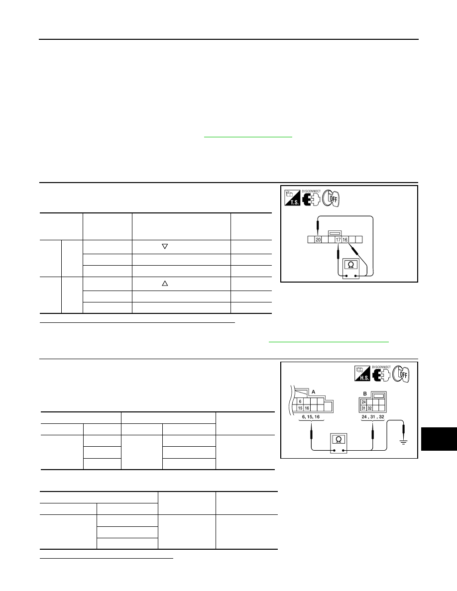
CHECK STEERING WHEEL AUDIO CONTROL SWITCH RESISTANCE

1. Disconnect steering wheel audio control switch connector M102.

2. Check resistance between steering switch connector terminals.

Do the steering wheel audio control switches check OK?

YES

>> GO TO 2

NO

>> Replace steering wheel audio control switch. Refer to 

AV-147, "Removal and Installation"

.

2.

CHECK HARNESS

1. Turn ignition switch OFF.

2. Disconnect AV control unit connector M131 and spiral cable

connector M30.

3. Check continuity between AV control unit harness connector

M131 (A) and spiral cable harness connector M30 (B).

4. Check continuity between AV control unit connector 1312 (A) and ground.

Are the continuity results as specified?

YES

>> GO TO 3

Terminal

Signal name

Condition

Resistance 

(

)

(Approx.)

16

17

Seek (down)

Depress  

switch.

165

Volume (down)

Depress VOL down switch.

487

Power

Depress PWR switch.

0

20

17

Seek (up)

Depress  

switch.

165

Volume (up)

Depress VOL up switch.

487

Mode

Depress MODE switch.

0

WKIA4457E

A

Continuity

Connector

Terminal

Connector

Terminal

M131

6

M30

24

Yes

15

31

16

32

A

Continuity

Connector

Terminal

M131

6

Ground

No

15

16

ALNIA0332GB

2010 Pathfinder

2010 Pathfinder

AV-96

< COMPONENT DIAGNOSIS >

[MID AUDIO]

STEERING SWITCH

NO

>> Repair harness.

3.

SPIRAL CABLE CHECK

1. Disconnect spiral cable connector M102.

2. Check continuity between spiral cable harness connector M30

(A) and M102 (B).

Is continuity present?

YES

>> Inspection End.

NO

>> Replace spiral cable. Refer to 

SR-7, "Removal and Installation"

.

A

B

Continuity

Connector

Terminal

Connector

Terminal

M30

24

M102

20

Yes

31

17

32

16

AWNIA1600ZZ

2010 Pathfinder

2010 Pathfinder

AV

COMMUNICATION SIGNAL CIRCUIT

AV-97

< COMPONENT DIAGNOSIS >

[MID AUDIO]

C

D

E

F

G

H

I

J

K

L

M

B

A

O

P

COMMUNICATION SIGNAL CIRCUIT

SATELLITE RADIO TUNER
SATELLITE RADIO TUNER : Description

INFOID:0000000005259339

Communication signals are exchanged between the AV control unit and satellite radio tuner using the commu-

nication circuits.

SATELLITE RADIO TUNER : Diagnosis Procedure

INFOID:0000000005259340

Regarding Wiring Diagram information, refer to 

AV-110, "Wiring Diagram"

.

1.

CHECK HARNESS - 1

1. Turn ignition switch OFF.

2. Disconnect satellite radio tuner (factory installed) connector M41

and AV control unit connector M43.

3. Check continuity between satellite radio tuner (factory installed)

harness connector M41 (A) terminal 28 and AV control unit har-

ness connector M43 (B) terminal 28.

4. Check continuity between satellite radio tuner (factory installed)

harness connector M41 (A) terminal 28 and ground.

Are continuity results as specified?

YES

>> GO TO 2

NO

>> Repair harness or connector.

2.

CHECK HARNESS - 2

1. Check continuity between satellite radio tuner (factory installed)

harness connector M41 (A) terminal 29 and AV control unit har-

ness connector M43 (B) terminal 29.

2. Check continuity between satellite radio tuner (factory installed)

harness connector M41 (A) terminal 29 and ground.

Are continuity results as specified?

YES

>> GO TO 3

NO

>> Repair harness or connector.

A

B

Continuity

Connector

Terminal

Connector

Terminal

M41

28

M43

28

Yes

A

Continuity

Connector

Terminal

M41

28

Ground

No

ALNIA0334GB

A

B

Continuity

Connector

Terminal

Connector

Terminal

M41

29

M43

29

Yes

A

Continuity

Connector

Terminal

M41

29

Ground

No

ALNIA0867GB

2010 Pathfinder

2010 Pathfinder

AV-98

< COMPONENT DIAGNOSIS >

[MID AUDIO]

COMMUNICATION SIGNAL CIRCUIT

3.

CHECK HARNESS - 3

1. Check continuity between satellite radio tuner (factory installed)

harness connector M41 (A) terminal 30 and AV control unit har-

ness connector M43 (B) terminal 30.

2. Check continuity between satellite radio tuner (factory installed)

harness connector M41 (A) terminal 30 and ground.

Are continuity results as specified?

YES

>> GO TO 4

NO

>> Repair harness or connector.

4.

CHECK REQ1 SIGNAL

1. Connect satellite radio tuner (factory installed) connector and AV control unit connector.

2. Turn ignition switch to ACC

3. Check signal between satellite radio tuner (factory installed) har-

ness connector M41 terminal 28 and ground with CONSULT-III

or oscilloscope.

Are voltage readings as specified?

YES

>> GO TO 5

NO

>> Replace AV control unit. Refer to 

AV-141, "Removal and Installation"

.

5.

CHECK TXD SIGNAL

Check signal between satellite radio tuner (factory installed) harness

connector M41 terminal 29 and ground with CONSULT-III or oscillo-

scope.

A

B

Continuity

Connector

Terminal

Connector

Terminal

M41

30

M43

30

Yes

A

Continuity

Connector

Terminal

M41

30

Ground

No

ALNIA0877GB

(+)

(-)

Reference signal

Connector

Terminal

M41

28

Ground

WKIA4544E

SKIB3825E

(+)

(-)

Reference signal

Connector

Terminal

M41

29

Ground

WKIA4545E

SKIB3824E

2010 Pathfinder

2010 Pathfinder

AV

COMMUNICATION SIGNAL CIRCUIT

AV-99

< COMPONENT DIAGNOSIS >

[MID AUDIO]

C

D

E

F

G

H

I

J

K

L

M

B

A

O

P

Are the voltage readings as specified?

YES

>> GO TO 6

NO

>> Replace satellite radio tuner. Refer to 

AV-154, "Removal and Installation"

.

6.

CHECK RXD SIGNAL

Check signal between satellite radio tuner (factory installed) harness

connector M41 terminal 30 and ground with CONSULT-III or oscillo-

scope.

Are the voltage readings as specified?

YES

>> Replace satellite radio tuner. Refer to 

AV-154, "Removal and Installation"

.

NO

>> Replace AV control unit. Refer to 

AV-141, "Removal and Installation"

.

(+)

(-)

Reference signal

Connector

Terminal

M41

30

Ground

WKIA4546E

SKIB3826E

2010 Pathfinder

2010 Pathfinder

AV-100

< COMPONENT DIAGNOSIS >

[MID AUDIO]

SOUND SIGNAL CIRCUIT

SOUND SIGNAL CIRCUIT

SATELLITE RADIO TUNER
SATELLITE RADIO TUNER : Description

INFOID:0000000005259341

Left and right channel audio signals are supplied from the satellite radio tuner to the AV control unit through

the sound signal circuits.

SATELLITE RADIO TUNER : Diagnosis Procedure

INFOID:0000000005259342

Regarding Wiring Diagram information, refer to 

AV-110, "Wiring Diagram"

.

LEFT CHANNEL

1.

CHECK HARNESS

1. Turn ignition switch OFF.

2. Disconnect satellite radio tuner (factory installed) connector M41

and AV control unit connector M43.

3. Check continuity between satellite radio tuner (factory installed)

connector M41 (A) and AV control unit connector M43 (B).

4. Check continuity between satellite radio tuner (factory installed) connector M41 (A) and ground.

Are continuity results as specified?

YES

>> GO TO 2

NO

>> Repair harness or connector.

2.

CHECK LEFT CHANNEL AUDIO SIGNAL

1. Connect satellite radio tuner (factory installed) and AV control

unit.

2. Turn ignition switch ON.

3. Check signal between satellite radio tuner (factory installed)

connector M41 terminals 21 and 22 with CONSULT-III or oscillo-

scope.

A

B

Continuity

Connector

Terminal

Connector

Terminal

M41

21

M43

21

Yes

22

22

A

Continuity

Connector

Terminal

M41

21

Ground

No

22

ALNIA0337GB

(+)

(-)

Reference signal

Connector

Terminal

M41

22

21

ALNIA0880GB

SKIB3609E

2010 Pathfinder

2010 Pathfinder

AV

SOUND SIGNAL CIRCUIT

AV-101

< COMPONENT DIAGNOSIS >

[MID AUDIO]

C

D

E

F

G

H

I

J

K

L

M

B

A

O

P

Are voltage readings as specified?

YES

>> Replace AV control unit. Refer to 

AV-141, "Removal and Installation"

.

NO

>> Replace satellite radio tuner. Refer to 

AV-154, "Removal and Installation"

.

RIGHT CHANNEL

1.

CHECK HARNESS

1. Turn ignition switch OFF.

2. Disconnect satellite radio tuner (factory installed) connector M41

and AV control unit connector M43.

3. Check continuity between satellite radio tuner (factory installed)

M41 (A) and AV control unit M43 (B).

4. Check continuity between satellite radio tuner (factory installed) connector M41 (A) and ground.

Are continuity results as specified?

YES

>> GO TO 2

NO

>> Repair harness or connector.

2.

CHECK RIGHT CHANNEL AUDIO SIGNAL

1. Connect satellite radio tuner (factory installed) and AV control

unit.

2. Turn ignition switch ON.

3. Check signal between satellite radio tuner (factory installed)

connector M41 terminals 23 and 24 with CONSULT-III or oscillo-

scope.

Are voltage readings as specified?

YES

>> Replace AV control unit. Refer to 

AV-141, "Removal and Installation"

.

NO

>> Replace satellite radio tuner. Refer to 

AV-154, "Removal and Installation"

.

A

B

Continuity

Connector

Terminal

Connector

Terminal

M41

23

M43

23

Yes

24

24

A

Continuity

Connector

Terminal

M41

23

Ground

No

24

ALNIA0338GB

(+)

(-)

Reference signal

Connector

Terminal

M41

24

23

ALNIA0881GB

SKIB3609E

2010 Pathfinder

2010 Pathfinder

AV-102

< ECU DIAGNOSIS >

[MID AUDIO]

AV CONTROL UNIT

ECU DIAGNOSIS

AV CONTROL UNIT

Reference Value

INFOID:0000000005259343

VALUES ON THE DIAGNOSIS TOOL

CONSULT-III data monitor item

TERMINAL LAYOUT

PHYSICAL VALUES

Display Item

Dis-
play

Vehicle status

Remarks

VHCL SPD SIG

ON

Vehicle speed >0 km/h (0 MPH)

Changes in indication may be delayed. This is nor-
mal.

OFF

Vehicle speed =0 km/h (0 MPH)

PKB SIG

ON

Parking brake is applied.

Changes in indication may be delayed. This is nor-
mal.

OFF

Parking brake is released.

ILLUM SIG

ON

Block the light beam from the auto 
light optical sensor when the light SW 
is ON .

OFF

Expose the auto light optical sensor 
to light when the light SW is OFF or 
ON.

IGN SIG

ON

Ignition switch ON

OFF

Ignition switch in ACC position

REV SIG

ON

Selector lever in R position

Changes in indication may be delayed. This is nor-
mal.

OFF

Selector lever in any position other 
than R

AWNIA0145ZZ

2010 Pathfinder

2010 Pathfinder


Content      ..     34      35      36      37     ..