Nissan Pathfinder (2009 year). Manual - part 477
BATTERY SAVER OUTPUT/POWER SUPPLY CIRCUIT
INL-17
< COMPONENT DIAGNOSIS >
C
D
E
F
G
H
I
J
K
M
A
B
INL
N
O
P
3.
Check continuity between BCM connector and each interior room lamp connector.
Is the inspection result normal?
YES
>> GO TO 3
NO
>> Repair the harness or connectors.
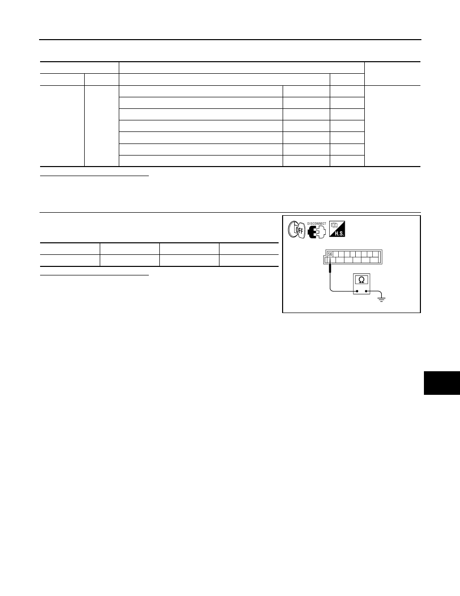
3.
CHECK BATTERY SAVER OUTPUT/POWER SUPPLY SHORT CIRCUIT
Check continuity between BCM connector M20 terminal 56 and
ground.
Is the inspection result normal?
YES
>> Check that each interior room lamp has no internal short
circuit.
NO
>> Repair the harness or connectors.
BCM
Each interior room lamp
Continuity
Connector
Terminal
Connector
Terminal
M20
56
Ignition keyhole illumination
M150
1
Yes
Front room/map lamp assembly
R9
1
Vanity lamp LH (if equipped)
B80
1
Vanity lamp RH (if equipped)
B81
1
Cargo lamp
R11
2
Personal lamp 2nd row (with personal lamp 2nd row)
R10
1
Room lamp 2nd row (without personal lamp 2nd row)
R12
2
Connector
Terminal
—
Continuity
M20
56
Ground
No
ALLIA0409GB
2009 Pathfinder