Nissan Pathfinder (2009 year). Manual - part 440


  Index      Manuals     Nissan Pathfinder (2009 year) - Service and Repair Manual


Search            copyright infringement  


Content      ..     438      439      440      441     ..


Nissan Pathfinder (2009 year). Manual - part 440


GI-58

< BASIC INSPECTION >

CONSULT-III CHECKING SYSTEM

x : Applicable

*1: With Intelligent Key

*2:With automatic drive positioner

*3: With rearview camera

*4: With 4-wheel drive

*5: With security card installed

CONSULT-III Data Link Connector (DLC) Circuit

INFOID:0000000003938081

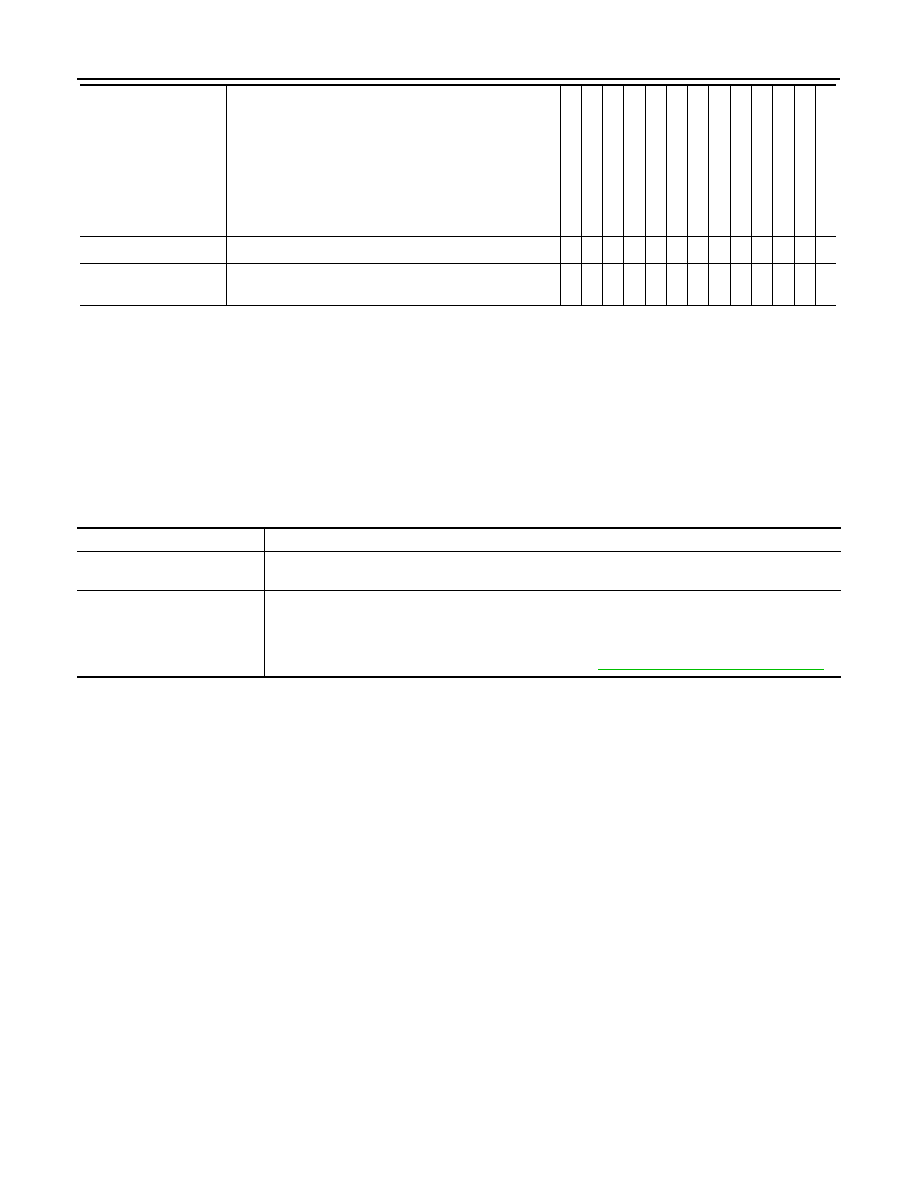
INSPECTION PROCEDURE

If the CONSULT-III cannot diagnose the system properly, check the following items.

NOTE:
The CAN and DDL2 circuits from DLC pins 6, 7 and 14 may be connected to more than one system. A short in
any circuit connected to a control unit in one system may affect CONSULT-III access to other systems.

PIN read

*5

This mode shows the BCM-specific 5-digit code.

-

-

-

-

-

x

-

-

-

-

-

-

-

Control unit

initialization

*5

All registered ignition key IDs in NATS components can be 
initialized and new IDs can be registered.

-

-

-

-

-

x

-

-

-

-

-

-

-

Diagnostic test mode

Function

ENGINE

TRANSMISS

ION

ABS

AIR B

A

G

IPDM E/R

BC

M

MET

E

R/M

&

A

INT

E

LL

IGENT KE

Y

*1

AUT

O

 DRIV

E

 POS.

*2

REAR

VIEW

 CAME

R

A

*3

MUL

T

I A

V

ALL MODE A

W

D/4WD

*4

HV

AC

Symptom

Check item

CONSULT-III cannot access 
any system.

• CONSULT-III DLC power supply circuit (Terminal 8) and ground circuit (Terminal 4) 

CONSULT-III cannot access in-
dividual system. (Other sys-
tems can be accessed.)

• Power supply and ground circuit for the control unit of the system (For detailed circuit, refer to wiring 

diagram for each system.)

• Open or short circuit between the system and CONSULT-III DLC (For detailed circuit, refer to wiring 

diagram for each system.)

• Open or short circuit CAN communication line. Refer to 

LAN-14, "Trouble Diagnosis Flow Chart"

.

2009 Pathfinder

CONSULT-III CHECKING SYSTEM

GI-59

< BASIC INSPECTION >

C

D

E

F

G

H

I

J

K

L

M

B

GI

N

O

P

Wiring Diagram

INFOID:0000000003938082

ABAWA0008GB

2009 Pathfinder

GW-1

BODY EXTERIOR, DOORS, ROOF & VEHICLE SECURITY

C

D

E

F

G

H

I

J

L

M

SECTION 

GW

A

B

GW

N

O

P

CONTENTS

GLASS & WINDOW SYSTEM

PRECAUTION ...............................................

2

PRECAUTIONS ...................................................

2

Precaution for Supplemental Restraint System 
(SRS) "AIR BAG" and "SEAT BELT PRE-TEN-
SIONER" .................................................................
..

2

Precaution Necessary for Steering Wheel Rota-
tion After Battery Disconnect ...................................
..

2

Handling for Adhesive and Primer  ............................

2

Precaution for Procedure without Cowl Top Cover 

......

3

PREPARATION ............................................

4

PREPARATION ...................................................

4

Special Service Tool  .................................................

4

Commercial Service Tool  ..........................................

4

SYMPTOM DIAGNOSIS  ...............................

5

SQUEAK AND RATTLE TROUBLE DIAG-
NOSES ................................................................

5

Work Flow  .................................................................

5

Generic Squeak and Rattle Troubleshooting ............

7

Diagnostic Worksheet ...............................................

9

REMOVAL AND INSTALLATION  ...............

11

WINDSHIELD GLASS .......................................

11

Removal and Installation  .........................................

11

FRONT DOOR GLASS AND REGULATOR .....

15

Front Door Glass  .....................................................

15

Front Door Glass Regulator .....................................

15

REAR DOOR GLASS AND REGULATOR  .......

19

Rear Door Glass ......................................................

19

Rear Door Glass Regulator  .....................................

19

SIDE WINDOW GLASS  ....................................

22

Removal and Installation  .........................................

22

GLASS HATCH .................................................

24

Removal and Installation  .........................................

24

2009 Pathfinder

GW-2

< PRECAUTION >

PRECAUTIONS

PRECAUTION

PRECAUTIONS

Precaution for Supplemental Restraint System (SRS) "AIR BAG" and "SEAT BELT 
PRE-TENSIONER"

INFOID:0000000003938564

The Supplemental Restraint System such as “AIR BAG” and “SEAT BELT PRE-TENSIONER”, used along
with a front seat belt, helps to reduce the risk or severity of injury to the driver and front passenger for certain
types of collision. This system includes seat belt switch inputs and dual stage front air bag modules. The SRS
system uses the seat belt switches to determine the front air bag deployment, and may only deploy one front
air bag, depending on the severity of a collision and whether the front occupants are belted or unbelted.
Information necessary to service the system safely is included in the SR and SB section of this Service Man-
ual.

WARNING:

• To avoid rendering the SRS inoperative, which could increase the risk of personal injury or death in

the event of a collision which would result in air bag inflation, all maintenance must be performed by
an authorized NISSAN/INFINITI dealer.

• Improper maintenance, including incorrect removal and installation of the SRS, can lead to personal

injury caused by unintentional activation of the system. For removal of Spiral Cable and Air Bag
Module, see the SR section.

• Do not use electrical test equipment on any circuit related to the SRS unless instructed to in this

Service Manual. SRS wiring harnesses can be identified by yellow and/or orange harnesses or har-
ness connectors.

Precaution Necessary for Steering Wheel Rotation After Battery Disconnect

INFOID:0000000004437752

NOTE:
• This Procedure is applied only to models with Intelligent Key system and NATS (NISSAN ANTI-THEFT SYS-

TEM).

• Remove and install all control units after disconnecting both battery cables with the ignition knob in the

LOCK

 position.

• Always use CONSULT-III to perform self-diagnosis as a part of each function inspection after finishing work.

If DTC is detected, perform trouble diagnosis according to self-diagnostic results.

For models equipped with the Intelligent Key system and NATS, an electrically controlled steering lock mech-
anism is adopted on the key cylinder.
For this reason, if the battery is disconnected or if the battery is discharged, the steering wheel will lock and
steering wheel rotation will become impossible.
If steering wheel rotation is required when battery power is interrupted, follow the procedure below before
starting the repair operation.

OPERATION PROCEDURE

1.

Connect both battery cables.
NOTE:
Supply power using jumper cables if battery is discharged.

2.

Use the Intelligent Key or mechanical key to turn the ignition switch to the 

ACC

 position. At this time, the

steering lock will be released.

3.

Disconnect both battery cables. The steering lock will remain released and the steering wheel can be
rotated.

4.

Perform the necessary repair operation.

5.

When the repair work is completed, return the ignition switch to the 

LOCK

 position before connecting

the battery cables. (At this time, the steering lock mechanism will engage.)

6.

Perform a self-diagnosis check of all control units using CONSULT-III. 

Handling for Adhesive and Primer

INFOID:0000000003938565

• Do not use an adhesive which is past its usable date. Shelf life of this product is limited to six months after

the date of manufacture. Carefully adhere to the expiration or manufacture date printed on the box.

• Keep primers and adhesive in a cool, dry place. Ideally, they should be stored in a refrigerator.

2009 Pathfinder

PRECAUTIONS

GW-3

< PRECAUTION >

C

D

E

F

G

H

I

J

L

M

A

B

GW

N

O

P

• Open the seal of the primer and adhesive just before application. Discard the remainder.
• Before application, be sure to shake the primer container to stir the contents. If any floating material is found,

do not use it.

• If any primer or adhesive contacts the skin, wipe it off with gasoline or equivalent and wash the skin with

soap.

• When using primer and adhesive, always observe the precautions in the instruction manual.

Precaution for Procedure without Cowl Top Cover

INFOID:0000000003938566

When performing the procedure after removing cowl top cover, cover
the lower end of windshield with urethane, etc.

PIIB3706J

2009 Pathfinder

GW-4

< PREPARATION >

PREPARATION

PREPARATION

PREPARATION

Special Service Tool

INFOID:0000000003938567

The actual shapes of Kent-Moore tools may differ from those of special service tools illustrated here.

Commercial Service Tool

INFOID:0000000003938568

Tool number
(Kent-Moore No.)
Tool name

Description

(J-39570)
Chassis ear

Locating the noise

(J-43980)
NISSAN Squeak and Rat-
tle Kit

Repairing the cause of noise

SIIA0993E

SIIA0994E

(Kent-Moore No.)
Tool name

Description

(J-39565)
Engine ear

Locating the noise 

(

)

Suction Lifter

Holding door glass 

SIIA0995E

LIIA1991E

2009 Pathfinder

SQUEAK AND RATTLE TROUBLE DIAGNOSES

GW-5

< SYMPTOM DIAGNOSIS >

C

D

E

F

G

H

I

J

L

M

A

B

GW

N

O

P

SYMPTOM DIAGNOSIS

SQUEAK AND RATTLE TROUBLE DIAGNOSES

Work Flow

INFOID:0000000003938569

CUSTOMER INTERVIEW

Interview the customer if possible, to determine the conditions that exist when the noise occurs. Use the Diag-
nostic Worksheet during the interview to document the facts and conditions when the noise occurs and any
customer's comments; refer to 

GW-9, "Diagnostic Worksheet"

. This information is necessary to duplicate the

conditions that exist when the noise occurs.
• The customer may not be able to provide a detailed description or the location of the noise. Attempt to obtain

all the facts and conditions that exist when the noise occurs (or does not occur).

• If there is more than one noise in the vehicle, be sure to diagnose and repair the noise that the customer is

concerned about. This can be accomplished by test driving the vehicle with the customer.   

• After identifying the type of noise, isolate the noise in terms of its characteristics. The noise characteristics

are provided so the customer, service adviser and technician are all speaking the same language when
defining the noise.

• Squeak —(Like tennis shoes on a clean floor)

Squeak characteristics include the light contact/fast movement/brought on by road conditions/hard surfaces
= higher pitch noise/softer surfaces = lower pitch noises/edge to surface = chirping. 

• Creak—(Like walking on an old wooden floor)

Creak characteristics include firm contact/slow movement/twisting with a rotational movement/pitch depen-
dent on materials/often brought on by activity.

• Rattle—(Like shaking a baby rattle)

Rattle characteristics include the fast repeated contact/vibration or similar movement/loose parts/missing
clip or fastener/incorrect clearance.

• Knock —(Like a knock on a door)

Knock characteristics include hollow sounding/sometimes repeating/often brought on by driver action.

• Tick—(Like a clock second hand)

Tick characteristics include gentle contacting of light materials/loose components/can be caused by driver
action or road conditions.

• Thump—(Heavy, muffled knock noise)

Thump characteristics include softer knock/dead sound often brought on by activity.

• Buzz—(Like a bumble bee)

Buzz characteristics include high frequency rattle/firm contact.

• Often the degree of acceptable noise level will vary depending upon the person. A noise that you may judge

as acceptable may be very irritating to the customer.

• Weather conditions, especially humidity and temperature, may have a great effect on noise level.

DUPLICATE THE NOISE AND TEST DRIVE

SBT842

2009 Pathfinder

GW-6

< SYMPTOM DIAGNOSIS >

SQUEAK AND RATTLE TROUBLE DIAGNOSES

If possible, drive the vehicle with the customer until the noise is duplicated. Note any additional information on
the Diagnostic Worksheet regarding the conditions or location of the noise. This information can be used to
duplicate the same conditions when you confirm the repair.
If the noise can be duplicated easily during the test drive, to help identify the source of the noise, try to dupli-
cate the noise with the vehicle stopped by doing one or all of the following:
1) Close a door.
2) Tap or push/pull around the area where the noise appears to be coming from.
3) Rev the engine.
4) Use a floor jack to recreate vehicle “twist”.
5) At idle, apply engine load (electrical load, half-clutch on M/T model, drive position on A/T model).
6) Raise the vehicle on a hoist and hit a tire with a rubber hammer.
• Drive the vehicle and attempt to duplicate the conditions the customer states exist when the noise occurs.
• If it is difficult to duplicate the noise, drive the vehicle slowly on an undulating or rough road to stress the

vehicle body.

CHECK RELATED SERVICE BULLETINS

After verifying the customer concern or symptom, check ASIST for Technical Service Bulletins (TSBs) related
to that concern or symptom.
If a TSB relates to the symptom, follow the procedure to repair the noise.

LOCATE THE NOISE AND IDENTIFY THE ROOT CAUSE

1.

Narrow down the noise to a general area.To help pinpoint the source of the noise, use a listening tool
(Chassis Ear: J-39570, Engine Ear: J-39565 and mechanic's stethoscope).

2.

Narrow down the noise to a more specific area and identify the cause of the noise by:

• removing the components in the area that you suspect the noise is coming from.

Do not use too much force when removing clips and fasteners, otherwise clips and fasteners can be broken
or lost during the repair, resulting in the creation of new noise.

• tapping or pushing/pulling the component that you suspect is causing the noise.

Do not tap or push/pull the component with excessive force, otherwise the noise will be eliminated only tem-
porarily.

• feeling for a vibration with your hand by touching the component(s) that you suspect is (are) causing the

noise.

• placing a piece of paper between components that you suspect are causing the noise.
• looking for loose components and contact marks.

Refer to 

GW-7, "Generic Squeak and Rattle Troubleshooting"

.

REPAIR THE CAUSE 

• If the cause is a loose component, tighten the component securely.
• If the cause is insufficient clearance between components:
- separate components by repositioning or loosening and retightening the component, if possible.
- insulate components with a suitable insulator such as urethane pads, foam blocks, felt cloth tape or urethane

tape. A NISSAN Squeak and Rattle Kit (J-43980) is available through your authorized NISSAN Parts Depart-
ment.

CAUTION:

Do not use excessive force as many components are constructed of plastic and may be damaged.
Always check with the Parts Department for the latest parts information.
The following materials are contained in the NISSAN Squeak and Rattle Kit (J-43980). Each item can be
ordered separately as needed.
URETHANE PADS [1.5 mm (0.059 in) thick]
Insulates connectors, harness, etc.
76268-9E005: 100

×

135 mm (3.94

×

5.31 in)/76884-71L01: 60

×

85 mm (2.36

×

3.35 in)/76884-71L02: 15

×

25

mm (0.59

×

0.98 in)

INSULATOR (Foam blocks)
Insulates components from contact. Can be used to fill space behind a panel.
73982-9E000: 45 mm (1.77 in) thick, 50

×

50 mm (1.97

×

1.97 in)/73982-50Y00: 10 mm (0.39 in) thick,

50

×

50 mm (1.97

×

1.97 in)

INSULATOR (Light foam block)
80845-71L00: 30 mm (1.18 in) thick, 30

×

50 mm (1.18

×

1.97 in)

FELT CLOTH TAPE
Used to insulate where movement does not occur. Ideal for instrument panel applications.

2009 Pathfinder


Content      ..     438      439      440      441     ..