Nissan Pathfinder (2009 year). Manual - part 426
DRIVE SHAFT
FAX-19
< DISASSEMBLY AND ASSEMBLY >
C
E
F
G
H
I
J
K
L
M
A
B
FAX
N
O
P
• Do not to touch the tip of the screwdriver to the inside of the boot.
9.
Secure the large and small ends of the boot with the new boot
bands as shown.
NOTE:
Discard the old boot bands and use new ones for assembly.
10. After installing the sliding joint housing to the drive shaft, rotate the boot to check that the boot is posi-
tioned correctly. If the boot is not positioned correctly, reposition the boot and secure the boot using a new
boot band.
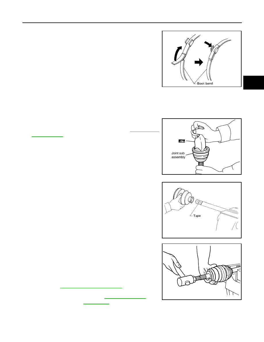
Wheel Side
1.
Insert the Genuine NISSAN Grease or equivalent, into the joint
sub-assembly serration hole until the grease begins to ooze
from the ball groove and serration hole. Refer to
. After inserting the grease, use a shop cloth to
wipe off the grease that has oozed out.
2.
Wrap the serrated part of the drive shaft with tape. Install the
boot band and boot onto the shaft. Do not damage the boot.
NOTE:
Discard the old boot band and boot and use a new one for
assembly.
3.
Remove the protective tape wound around the serrated part of
the drive shaft.
4.
Attach the circlip to the drive shaft. The circlip must fit securely
into the drive shaft groove. Attach the nut to the joint sub-assem-
bly.
Use a soft hammer to press-fit the circlip.
NOTE:
Discard the old circlip and use a new one for assembly.
5.
Insert the specified quantity of Genuine NISSAN Grease or
equivalent, into the joint sub-assembly and the large end of the
boot. Refer to
MA-12, "Fluids and Lubricants"
SFA395
SDIA1127E
SFA800
Grease capacity
: Refer to
RAC0049D
2009 Pathfinder