Nissan Pathfinder (2009 year). Manual - part 423
EXT-22
< ON-VEHICLE REPAIR >
FENDER PROTECTOR
FENDER PROTECTOR
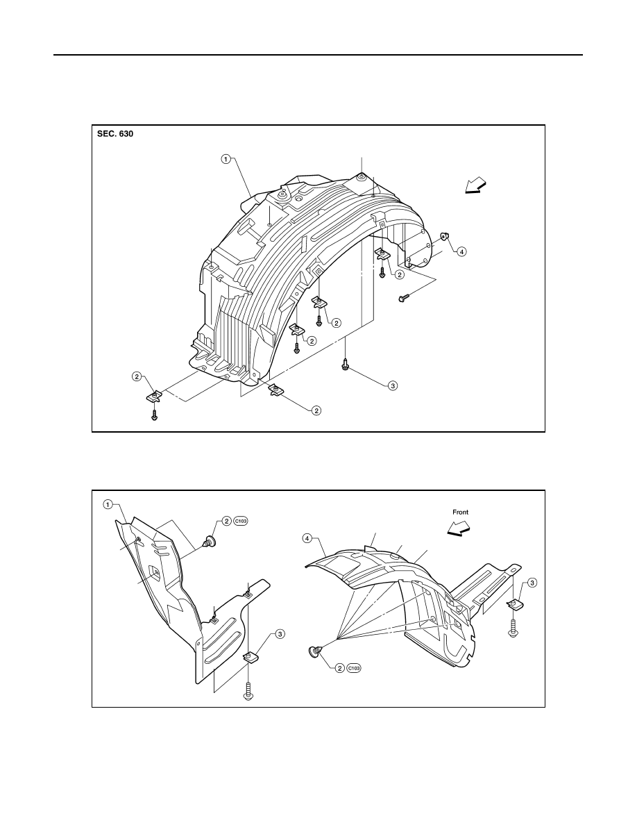
Component
INFOID:0000000003938697
Front Fender Protector
Rear Fender Protector
Removal and Installation of Front Fender Protector
INFOID:0000000003938698
REMOVAL
WIIA1078E
1.
Front fender protector LH shown
2.
Nut
3.
Clip C205
4.
Grommet
⇐
Vehicle front
LIIA1764E
1.
Rear fender protector RH
2.
Clips
3.
Nuts
4.
Rear fender protector LH
2009 Pathfinder