Nissan Pathfinder (2009 year). Manual - part 405


  Index      Manuals     Nissan Pathfinder (2009 year) - Service and Repair Manual


Search            copyright infringement  


Content      ..     403      404      405      406     ..


Nissan Pathfinder (2009 year). Manual - part 405


EXL-30

< FUNCTION DIAGNOSIS >

DIAGNOSIS SYSTEM (IPDM E/R)

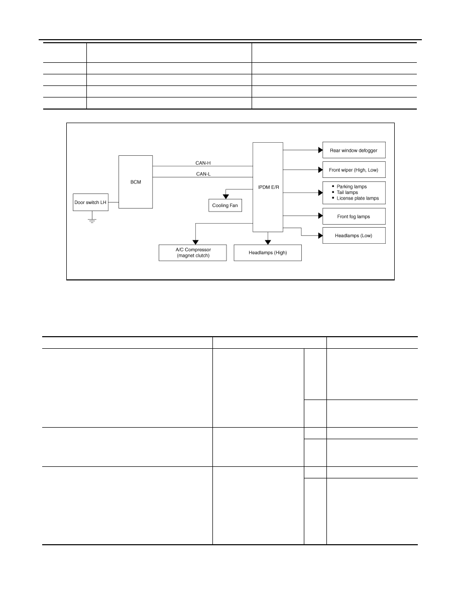
Concept of auto active test

• IPDM E/R starts the auto active test with the door switch signals transmitted by BCM via CAN communica-

tion. Therefore, the CAN communication line between IPDM E/R and BCM is considered normal if the auto
active test starts successfully.

• The auto active test facilitates troubleshooting if any systems controlled by IPDM E/R cannot be operated.

Diagnosis chart in auto active test mode

3

Tail, license, front fog and parking lamps

10 seconds

4

Headlamps

LO for 10 seconds 

 HI on-off for 5 seconds

5

A/C compressor (magnetic clutch)

ON 

 OFF 5 times

6

Cooling fan

10 seconds

Operation 
sequence

Inspection Location

Operation

WKIA5163E

Symptom

Inspection contents

Possible cause

Oil pressure low warning indicator does not operate

Perform auto active test.
Does the oil pressure low 
warning indicator operate?

YES

• IPDM E/R signal input cir-

cuit

• ECM signal input circuit
• CAN communication signal 

between ECM and combi-
nation meter

NO

• CAN communication signal 

between IPDM E/R, BCM 
and combination meter

Oil pressure gauge does not operate

Perform auto active test.
Does the oil pressure gauge 
operate?

YES

IPDM E/R signal input circuit

NO

• CAN communication signal 

between IPDM E/R, BCM 
and combination meter

Rear window defogger does not operate

Perform auto active test.
Does the rear window defog-
ger operate?

YES

BCM signal input circuit

NO

• Harness or connector be-

tween A/C and AV switch 
assembly and AV control 
unit

• CAN communication signal 

between BCM and IPDM E/
R

2009 Pathfinder

DIAGNOSIS SYSTEM (IPDM E/R)

EXL-31

< FUNCTION DIAGNOSIS >

C

D

E

F

G

H

I

J

K

M

A

B

EXL

N

O

P

CONSULT - III Function (IPDM E/R)

INFOID:0000000004422059

APPLICATION ITEM

CONSULT-III performs the following functions via CAN communication with IPDM E/R.

SELF DIAGNOSTIC

Refer to 

PCS-31, "DTC Index"

.

DATA MONITOR

Monitor item

Any of the following components do not operate

• Front wipers
• Tail  lamps
• License plate lamps
• Parking  lamps
• Front fog lamps
• Headlamps (Hi, Lo)

Perform auto active test.
Does the applicable system 
operate?

YES

BCM signal input system

NO

• Lamp or front wiper motor 

malfunction

• Lamp or front wiper motor 

ground circuit

• Harness or connector be-

tween IPDM E/R and appli-
cable system

• IPDM E/R (integrated relay 

malfunction)

A/C compressor does not operate

Perform auto active test.
Does the A/C compressor op-
erate?

YES

• BCM signal input circuit
• CAN communication signal 

between BCM and ECM

• CAN communication signal 

between ECM and IPDM E/
R

NO

• Magnetic clutch malfunction
• Harness or connector be-

tween IPDM E/R and mag-
netic clutch

• IPDM E/R (integrated relay 

malfunction)

Cooling fan does not operate

Perform auto active test.
Does the cooling fan operate?

YES

• ECM signal input circuit
• CAN communication signal 

between ECM and IPDM E/
R

NO

• Cooling fan motor malfunc-

tion

• Harness or connector be-

tween IPDM E/R and cool-
ing fan

• IPDM E/R (integrated relay 

malfunction)

Symptom

Inspection contents

Possible cause

Diagnosis mode

Description

ECU Identification

Allows confirmation of IPDM E/R part number.

Self Diagnostic Result

Displays the diagnosis results judged by IPDM E/R.

Data Monitor

Displays the real-time input/output data from IPDM E/R input/output data.

Active Test

IPDM E/R can provide a drive signal to electronic components to check their operations.

CAN Diag Support Monitor

The results of transmit/receive diagnosis of CAN communication can be read.

2009 Pathfinder

EXL-32

< FUNCTION DIAGNOSIS >

DIAGNOSIS SYSTEM (IPDM E/R)

ACTIVE TEST

Test item

Monitor Item

[Unit]

MAIN SIG-

NALS

Description

MOTOR FAN REQ
[1/2/3/4]

×

Displays the status of the cooling fan speed request signal received from ECM via 
CAN communication.

A/C COMP REQ
[OFF/ON]

×

Displays the status of the A/C request signal received from AV control unit via 
CAN communication.

TAIL&CLR REQ
[OFF/ON]

×

Displays the status of the position light request signal received from BCM via CAN 
communication.

HL LO REQ
[OFF/ON]

×

Displays the status of the low beam request signal received from BCM via CAN 
communication.

HL HI REQ
[OFF/ON]

×

Displays the status of the high beam request signal received from BCM via CAN 
communication.

FR FOG REQ
[OFF/ON]

×

Displays the status of the front fog lamp request signal received from BCM via 
CAN communication.

HL WASHER REQ
[OFF/ON]

NOTE:
This item is displayed, but cannot be monitored.

FR WIP REQ
[STOP/1LOW/LOW/HI]

×

Displays the status of the front wiper request signal received from BCM via CAN 
communication.

WIP AUTO STOP
[STOP P/ACT P]

×

Displays the status of the front wiper auto stop signal judged by IPDM E/R.

WIP PROT
[OFF/Block]

×

Displays the status of the front wiper fail-safe operation judged by IPDM E/R.

ST RLY REQ
[OFF/ON]

Displays the status of the starter request signal received from ECM via CAN com-
munication.

IGN RLY
[OFF/ON]

×

Displays the status of the ignition relay judged by IPDM E/R.

RR DEF REQ
[OFF/ON]

×

Displays the status of the rear defogger request signal received from AV control 
unit via CAN communication.

OIL P SW
[OPEN/CLOSE]

Displays the status of the oil pressure switch judged by IPDM E/R.

DTRL REQ
[OFF]

NOTE:
This item is displayed, but cannot be monitored.

HOOD SW
[OPEN/CLOSE]

NOTE:
This item is displayed, but cannot be monitored.

THFT HRN REQ
[OFF/ON]

Displays the status of the theft warning horn request signal received from BCM 
via CAN communication.

HORN CHIRP
[OFF/ON]

Displays the status of the horn reminder signal received from BCM via CAN com-
munication.

Test item

Operation

Description

REAR DEFOGGER

OFF

OFF

ON

Operates rear window defogger relay.

FRONT WIPER

OFF

OFF

LO

Operates the front wiper relay.

HI

Operates the front wiper relay and front wiper high relay.

HEAD LAMP WASHER

ON

2009 Pathfinder

DIAGNOSIS SYSTEM (IPDM E/R)

EXL-33

< FUNCTION DIAGNOSIS >

C

D

E

F

G

H

I

J

K

M

A

B

EXL

N

O

P

MOTOR FAN

1

OFF

2

OFF

3

Operates the cooling fan relay.

4

Operates the cooling fan relay.

EXTERNAL LAMPS

OFF

OFF

TAIL

Operates the tail lamp relay.

LO

Operates the headlamp low relay.

HI

Operates the headlamp low relay and ON/OFF the headlamp high relay at 1 sec-
ond intervals.

FOG

Operates the front fog lamp relay

HORN

ON

Operates horn relay for 20 ms.

Test item

Operation

Description

2009 Pathfinder

EXL-34

< COMPONENT DIAGNOSIS >

POWER SUPPLY AND GROUND CIRCUIT

COMPONENT DIAGNOSIS

POWER SUPPLY AND GROUND CIRCUIT

BCM (BODY CONTROL MODULE)

BCM (BODY CONTROL MODULE) : Diagnosis Procedure

INFOID:0000000004422064

1.

 CHECK FUSES AND FUSIBLE LINK

Check that the following fuses and fusible link are not blown.

Is the fuse blown?

YES

>> Replace the blown fuse or fusible link after repairing the affected circuit.

NO

>> GO TO 2

2.

 CHECK POWER SUPPLY CIRCUIT

1.

Turn ignition switch OFF.

2.

Disconnect BCM.

3.

Check voltage between BCM harness connector and ground.

Is the measurement value normal?

YES

>> GO TO 3

NO

>> Repair or replace harness.

3.

 CHECK GROUND CIRCUIT

Check continuity between BCM harness connector and ground.

Does continuity exist?

YES

>> Inspection End.

NO

>> Repair or replace harness.

Terminal No.

Signal name

Fuses and fusible link No.

57

Battery power supply

18 (10A)

70

G (50A)

11

Ignition ACC or ON

4 (10A)

38

Ignition ON or START

1 (10A)

Connector

Terminals 

Power

source

Condition

Voltage (V) (Ap-

prox.)

(+)

(-)

M18

11

Ground

ACC 

power 

supply

Ignition 

switch 

ACC or 

ON

Battery voltage

38

Ground

Ignition 

power 

supply

Ignition 

switch ON 

or START

Battery voltage

M20

57

Ground

Battery 

power 

supply

Ignition 

switch 

OFF

Battery voltage

70

Ground

Battery 

power 

supply

Ignition 

switch 

OFF

Battery voltage

LIIA2415E

BCM

Ground

Continuity

Connector

Terminal

M20

67

Yes

LIIA0915E

2009 Pathfinder

POWER SUPPLY AND GROUND CIRCUIT

EXL-35

< COMPONENT DIAGNOSIS >

C

D

E

F

G

H

I

J

K

M

A

B

EXL

N

O

P

IPDM E/R (INTELLIGENT POWER DISTRIBUTION MODULE ENGINE ROOM)

IPDM E/R (INTELLIGENT POWER DISTRIBUTION MODULE ENGINE ROOM) : Di-
agnosis Procedure

INFOID:0000000004427400

1.

 CHECK FUSES AND FUSIBLE LINK

Check that the following IPDM E/R fuses or fusible link are not blown.

Is the fuse blown?

YES

>> Replace the blown fuse or fusible link after repairing the affected circuit.

NO

>> GO TO 2

2.

 CHECK BATTERY POWER SUPPLY CIRCUIT

1.

Turn ignition switch OFF.

2.

Disconnect IPDM E/R.

3.

Check voltage between IPDM E/R harness connectors and
ground.

Is the measurement value normal?

YES

>> GO TO 3

NO

>> Repair or replace harness.

3.

 CHECK GROUND CIRCUIT

1.

Turn ignition switch OFF.

2.

Check continuity between IPDM E/R harness connectors and
ground.

Does continuity exist?

YES

>> Inspection End.

NO

>> Repair or replace harness.

Terminal No.

Signal name

Fuses and fusible link No.

1

Battery

A, D

2

Battery

C

Terminals

Ignition switch position

(+)

(

)

OFF

ON

START

Connector

Terminal

E118

1

Ground

Battery
voltage

Battery
voltage

Battery
voltage

2

Battery
voltage

Battery
voltage

Battery
voltage

SKIA1987E

IPDM E/R

Ground

Continuity

Connector

Terminal

E122 (A)

38

Yes

E124 (B)

59

AWMIA0024ZZ

2009 Pathfinder

EXL-36

< COMPONENT DIAGNOSIS >

HEADLAMP (HI) CIRCUIT

HEADLAMP (HI) CIRCUIT

Description

INFOID:0000000003939614

The IPDM E/R (intelligent power distribution module engine room) controls the headlamp high relay based on
inputs from the BCM via the CAN communication lines. When the headlamp high relay is energized, power
flows through fuses 34 and 35, located in the IPDM E/R. Power then flows to the front combination lamps to
the headlamp high beam.

Component Function Check

INFOID:0000000003939615

1.

CHECK HEADLAMP (HI) OPERATION

WITHOUT CONTULT-III

1.

Start IPDM E/R auto active test. Refer to 

PCS-12, "Diagnosis Description"

.

2.

Check that the headlamp switches to the high beam.
NOTE:
HI/LO is repeated 1 second each when using the IPDM E/R auto active test.

CONSULT-III

1.

Select "EXTERNAL LAMP" of IPDM E/R active test item.

2.

With the test item operating, check that the headlamp switches to high beam.

Does the headlamp switch to high beam?

YES

>> Headlamp (HI) circuit is normal.

NO

>> Refer to 

EXL-36, "Diagnosis Procedure"

.

Diagnosis Procedure

INFOID:0000000003939616

1.

CHECK HEADLAMP (HI) FUSES

1.

Turn the ignition switch OFF.

2.

Check that the following fuses are not open.

Is the fuse open?

YES

>> Repair the harness and replace the fuse.

NO

>> GO TO 2

2.

CHECK HEADLAMP (HI) OUTPUT VOLTAGE

1.

Turn the ignition switch OFF.

2.

Disconnect the front combination lamp connector E11 or E107.

3.

Turn the ignition switch ON.

4.

Turn the high beam headlamps ON.

5.

With the high beam headlamps ON, check the voltage between
the combination lamp connector and ground.

Is battery voltage present?

YES

>> GO TO 4

NO

>> GO TO 3

HI

: Headlamp switches to the high beam.

OFF

: Headlamp OFF

Unit

Location

Fuse No.

Capacity

Headlamp HI (LH) 

IPDM E/R

34

10A

Headlamp HI (RH) 

IPDM E/R

35

10A

(+)

(

)

Voltage

Connector

Terminal

LH

E11

1

Ground

Battery voltage

RH

E107

1

WKIA4989E

2009 Pathfinder

HEADLAMP (HI) CIRCUIT

EXL-37

< COMPONENT DIAGNOSIS >

C

D

E

F

G

H

I

J

K

M

A

B

EXL

N

O

P

3.

CHECK HEADLAMP (HI) CIRCUIT FOR OPEN

1.

Turn the ignition switch OFF.

2.

Disconnect IPDM E/R connector E123.

3.

Check continuity between the IPDM E/R harness connector (A)
and the front combination lamp harness connector (B).

Does continuity exist?

YES

>> GO TO 4

NO

>> Repair the harnesses or connectors.

4.

CHECK FRONT COMBINATION LAMP (HI) GROUND CIRCUIT

Check continuity between the front combination lamp harness con-
nector terminal and ground.

Does continuity exist?

YES

>> Inspect the headlamp bulb.

NO

>> Repair the harness.

A

B

Continuity

Connector

Terminal

Connector

Terminal

LH

E123

55

E11

1

Yes

RH

56

E107

1

ALLIA0623GB

Connector

Terminal

Continuity

LH

E11

2

Ground

Yes

RH

E107

2

ALLIA0624GB

2009 Pathfinder


Content      ..     403      404      405      406     ..