Nissan Pathfinder (2009 year). Manual - part 395
CYLINDER HEAD
EM-217
< ON-VEHICLE REPAIR >
[VK56DE]
C
D
E
F
G
H
I
J
K
L
M
A
EM
N
P
O
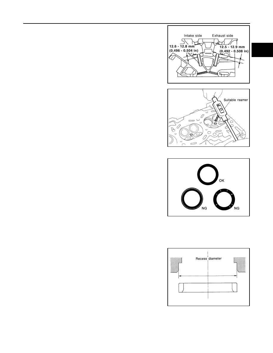
5.
Press the valve guide from the camshaft side to the dimensions
as shown.
WARNING:
Cylinder head contains heat. When working, wear protec-
tive equipment to avoid getting burned.
6.
Ream the cylinder head valve guide using suitable tool.
VALVE SEAT CONTACT
• After confirming that the dimensions of the valve guides and valves
are within specifications, perform this procedure.
• Apply prussian blue (or white lead) onto the contacting surface of
the valve seat to check the condition of the valve contact on the
surface.
• Check if the contact area band is continuous all around the circum-
ference.
• If not, grind to adjust the valve fit and check again. If the contacting
surface still has NG conditions even after the re-check, replace the
valve seat.
VALVE SEAT REPLACEMENT
When the valve seat is removed, replace it with oversized (0.5 mm, 0.020 in) valve seat.
1.
Bore out the old seat until it collapses. Boring should not continue beyond the bottom face of the seat
recess in the cylinder head. Set the machine depth stop to ensure this.
2.
Ream the cylinder head recess diameter for service valve seat.
• Be sure to ream in circles concentric to the valve guide center.
• This will enable valve seat to fit correctly.
KBIA2530E
Valve guide hole diameter:
Intake and exhaust
: 6.000 - 6.018 mm (0.2362
- 0.2369 in)
SEM932C
SBIA0322E
Oversize [0.5 mm (0.020 in)] (Service):
Intake
: 38.500 - 38.516 mm (1.5157 - 1.5164 in)
Exhaust
: 32.700 - 32.716 mm (1.2874 - 1.2880 in)
SEM795A
2009 Pathfinder