Nissan Pathfinder (2009 year). Manual - part 390


  Index      Manuals     Nissan Pathfinder (2009 year) - Service and Repair Manual


Search            copyright infringement  


Content      ..     388      389      390      391     ..


Nissan Pathfinder (2009 year). Manual - part 390


OIL PAN AND OIL STRAINER

EM-177

< ON-VEHICLE REPAIR >

[VK56DE]

C

D

E

F

G

H

I

J

K

L

M

A

EM

N

P

O

6.

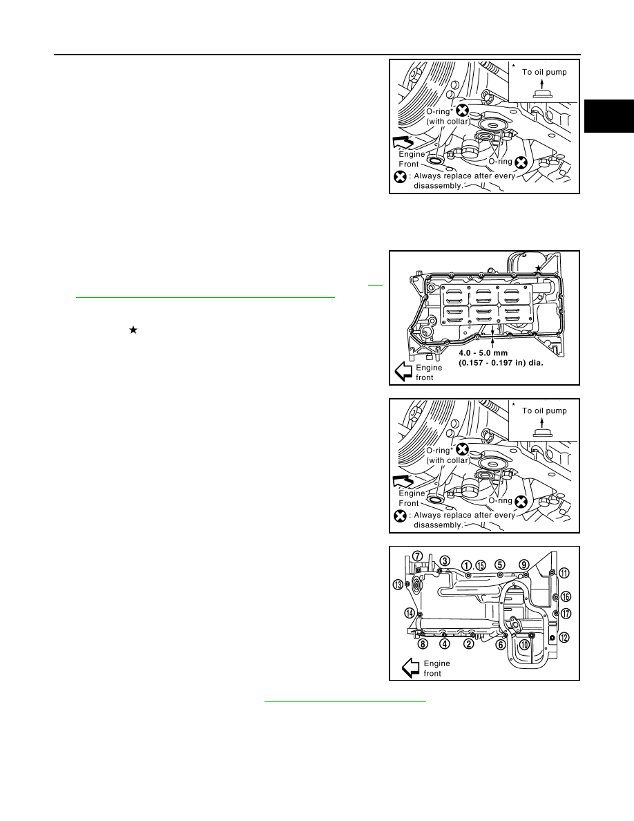
Remove the O-rings from the oil pump and front cover.

INSPECTION AFTER REMOVAL

Clean the oil strainer.

INSTALLATION

1.

Install the oil pan (upper) using the following steps.

a.

Apply liquid gasket thoroughly as shown.
Use Genuine RTV Silicone Sealant or equivalent. Refer to 

GI-

26, "Recommended Chemical Products and Sealants"

.

CAUTION:

Apply liquid gasket to outside of bolt hole for the hole
shown by  .

b.

Install new O-rings to the oil pump and front cover side.
NOTE:
Do not reuse O-rings.

c.

Tighten the bolts in numerical order as shown.

2.

Install the oil strainer to the oil pan (upper).

3.

Install the oil cooler assembly. Refer to 

LU-28, "Removal and Installation"

.

KBIA2469E

KBIA2470E

KBIA2469E

M6 

×

 30 mm (1.18 in)

: No. 15, 16

M8 

×

 25 mm (0.98in)

: No. 1, 3, 5, 7, 11, 13

M8 

×

 45 mm (1.77 in)

: No. 2, 4, 6, 8, 10, 14

M8 

×

 123 mm (4.84in)

: No. 9, 12

PBIC2553E

2009 Pathfinder

EM-178

< ON-VEHICLE REPAIR >

[VK56DE]

OIL PAN AND OIL STRAINER

4.

Install the oil pan (lower).

a.

Apply liquid gasket thoroughly as shown.
Use Genuine RTV Silicone Sealant or equivalent. Refer to

GI-26, "Recommended Chemical Products and Sealants"

CAUTION:

Attaching should be done within 5 minutes after coating.

b.

Tighten the oil pan (lower) bolts in numerical order as shown.

5.

Install the oil pan drain plug.

6.

Install engine assembly. Refer to 

EM-220, "Removal and Installation"

.

• Do not fill the engine with oil for at least 30 minutes after oil pan is installed.

INSPECTION AFTER INSTALLATION

1.

Check engine oil level and add engine oil if necessary. Refer to 

LU-24, "Inspection"

.

2.

Start the engine, and check for leaks of engine oil.

3.

Stop engine and wait for 10 minutes.

4.

Check engine oil level again.

KBIA2471E

PBIC2595E

2009 Pathfinder

IGNITION COIL

EM-179

< ON-VEHICLE REPAIR >

[VK56DE]

C

D

E

F

G

H

I

J

K

L

M

A

EM

N

P

O

IGNITION COIL

Exploded View

INFOID:0000000003939554

Removal and Installation

INFOID:0000000003939555

REMOVAL

1.

Remove the engine room cover using power tool. Refer to 

EM-166, "Removal and Installation"

.

2.

Remove the air duct and resonator assembly. Refer to 

EM-167, "Removal and Installation"

.

3.

Disconnect the harness connector from the ignition coil.

4.

Remove the ignition coil.

CAUTION:

Do not shock ignition coil.

INSTALLATION

Installation is in the reverse order of removal.

1.

Ignition coil

2.

Spark plug

WBIA0796E

2009 Pathfinder

EM-180

< ON-VEHICLE REPAIR >

[VK56DE]

ROCKER COVER

ROCKER COVER

Exploded View

INFOID:0000000003939556

Removal and Installation

INFOID:0000000003939557

REMOVAL

1.

Remove the engine room cover using power tool. Refer to 

EM-166, "Removal and Installation"

.

2.

Remove the air duct and resonator assembly. Refer to 

EM-167, "Removal and Installation"

 (for LH only).

3.

Move the harness on the upper rocker cover and its peripheral aside.

4.

Remove the electric throttle control actuator, loosening the bolts diagonally (for LH only).

5.

Remove the ignition coils. Refer to 

EM-179, "Removal and Installation"

.

6.

Remove the PCV hose from the PCV control valves.

7.

Loosen the rocker cover bolts in reverse order shown using
power tool.

: Engine front

• A: Rocker cover (LH)
• B: Rocker cover (RH)

CAUTION:

Do not hold the rocker cover (RH) (B) by the oil filler neck.

INSTALLATION

1.

Rocker cover (LH)

2.

PCV control valve

3.

O-ring

4.

Rocker cover gasket (LH)

5.

Rocker cover (RH)

6.

PCV control valve

7.

O-ring

8.

Oil filler cap

9.

Rocker cover gasket (RH)

KBIA2508E

WBIA0697E

2009 Pathfinder

ROCKER COVER

EM-181

< ON-VEHICLE REPAIR >

[VK56DE]

C

D

E

F

G

H

I

J

K

L

M

A

EM

N

P

O

1.

Apply liquid gasket to the joint part of the cylinder head and
camshaft bracket following the steps below.
NOTE:
Illustration shows an example of (LH) side (zoomed in shows
No.1 camshaft bracket).

a.

Apply liquid gasket to the joint part of No.1 camshaft bracket and
cylinder head "a".

b.

Apply liquid gasket 90

°

 "b" to illustration 

a

.

Use Genuine RTV Silicone Sealant or equivalent. Refer to

GI-26, "Recommended Chemical Products and Sealants"

.

2.

Install the rocker cover and tighten the bolts in two steps in the
order shown.

: Engine front 

• A: Rocker cover (LH)
• B: Rocker cover (RH)

CAUTION:

• Do not hold the rocker cover (RH) (B) by the oil filler neck.
• Make sure the new rocker cover gasket is installed in the

groove of the rocker cover.

3.

Install the PCV hoses.
NOTE:
• Remove foreign materials from inside the hose using compressed air.
• The inserted length is within 25 - 30 mm (0.98 - 1.18 in) [Target: 25 mm (0.98 in)].

4.

Installation of the remaining components is in the reverse order of removal.

KBIA2510E

1st step

: 2.0 N·m (0.2 kg-m, 18 in-lb)

2nd step

: 8.3 N·m (0.85 kg-m, 73 in-lb)

WBIA0697E

2009 Pathfinder

EM-182

< ON-VEHICLE REPAIR >

[VK56DE]

FUEL INJECTOR AND FUEL TUBE

FUEL INJECTOR AND FUEL TUBE

Exploded View

INFOID:0000000003939558

Removal and Installation

INFOID:0000000003939559

CAUTION:

Do not remove or disassemble parts unless instructed as shown.

REMOVAL

WARNING:

• Put a “CAUTION FLAMMABLE” sign in the workshop.
• Be sure to work in a well ventilated area and furnish workshop with a CO

2

 fire extinguisher.

• Do not smoke while servicing fuel system. Keep open flames and sparks away from the work area.
• To avoid the danger of being scalded, do not drain engine coolant when engine is hot.

1.

Remove the engine room cover using power tool. Refer to 

EM-166, "Removal and Installation"

.

2.

Release the fuel pressure. Refer to 

EC-951, "Fuel Pressure Check"

.

3.

Remove the air duct and resonator assembly. Refer to 

EM-167, "Removal and Installation"

.

4.

Disconnect the fuel injector harness connectors.

5.

Disconnect the fuel hose assembly from the fuel tubes (RH and LH).

CAUTION:

• While hoses are disconnected, plug them to prevent fuel from draining.
• Do not separate the fuel connector and fuel hose.

1.

Fuel tube (RH)

2.

Cap

3.

Fuel damper

4.

O-ring

5.

O-ring (blue)

6.

Fuel injector

7.

Clip

8.

O-ring (brown)

9.

O-ring

10.

Fuel hose assembly

11. Fuel tube (LH)

KBIA2472E

2009 Pathfinder

FUEL INJECTOR AND FUEL TUBE

EM-183

< ON-VEHICLE REPAIR >

[VK56DE]

C

D

E

F

G

H

I

J

K

L

M

A

EM

N

P

O

6.

Remove the fuel injectors with the fuel tube assembly.

7.

Remove the fuel injector from the fuel tube.

a.

Spread open to remove the clip.

b.

Remove the fuel injector from the fuel tube by pulling straight
out.

CAUTION:

• Be careful with remaining fuel that may leak out from fuel

tube.

• Do not damage injector nozzles during removal.
• Do not bump or drop fuel injectors.
• Do not disassemble fuel injectors.

8.

Remove the fuel damper from each fuel tube.

INSTALLATION

1.

Install the fuel damper to each fuel tube.

a.

Apply engine oil to the new O-ring and set it into the cup of the
fuel tube.

CAUTION:

• Handle O-ring with bare hands. Never wear gloves.
• Lubricate new O-ring with new engine oil.
• Do not clean O-ring with solvent.
• Make sure that O-ring and its mating part are free of for-

eign material.

• When installing O-ring, do not scratch it with tool or fin-

gernails.

• Do not twist or stretch the O-ring.

b.

Make sure that the backup spacer is in the O-ring connecting surface of the fuel damper.
NOTE:
The backup spacer is part of the fuel damper assembly.

c.

Insert the fuel damper until it seats on the fuel tube.

CAUTION:

• Insert straight, making sure that the axis is lined up.
• Do not pressure-fit with excessive force.

d.

Install the cap, and then tighten the bolts evenly.
• After tightening the bolts, make sure that there is no gap between the cap and fuel tube.

2.

Install new O-rings to the fuel injector paying attention to the items below.

CAUTION:

• Do not reuse O-rings.
• Upper and lower O-rings are different colors. 

KBIA2506E

Reference value

:130 N (13.3 kg, 29.2 lb)

Fuel tube side

: Blue

Nozzle side

: Brown

KBIA2473E

2009 Pathfinder

EM-184

< ON-VEHICLE REPAIR >

[VK56DE]

FUEL INJECTOR AND FUEL TUBE

• Handle O-ring with bare hands. Never wear gloves.
• Lubricate new O-ring with new engine oil.
• Do not clean O-ring with solvent.
• Make sure that O-ring and its mating part are free of foreign material.
• When installing O-ring, be careful not to scratch it with tool or fingernails. Also be careful not to

twist or stretch O-ring. 

• If O-ring was stretched while it was being attached, do not insert it quickly into fuel tube.
• Insert O-ring straight into fuel tube. Do not angle or twist it.

3.

Install the fuel injector to the fuel tube.

a.

Insert new clip into clip mounting groove on the fuel injector.
• Insert clip so that lug 

A

 of fuel injector matches notch 

A

 of

the clip.

CAUTION:

• Do not reuse clip. Replace it with a new one.
• Do not allow the clip to interfere with the O-ring. If inter-

ference occurs, replace the O-ring.

b.

Insert the fuel injector into the fuel tube with the clip attached.
• Insert it while matching it to the axial center.
• Insert fuel injector so that lug 

B

 of fuel tube matches notch

B

 of the clip.

• Make sure that the fuel tube flange is securely seated in the

flange fixing groove on the clip.

c.

Make sure that installation is complete by checking that the fuel
injector does not rotate or come off.
• Make sure that the protrusions of the fuel injectors are aligned

with the cutouts of the clips after installation.

4.

Install the fuel tube and fuel injector assembly to the intake manifold.

CAUTION:

Do not let the tip of the injector nozzle come in contact with other parts.
• Tighten fuel tube assembly bolts 

a

 to 

b

 in illustration in two

steps.

5.

Install the fuel hose assembly.
• Insert connectors straight, making sure that the axis is lined up with fuel tube side to prevent O-ring from

being damaged.

• Tighten bolts evenly in several steps.
• Make sure that there is no gap between the flange and fuel tube after tightening the bolts.

CAUTION:

• Handle O-ring with bare hands. Do not wear gloves.
• Lubricate O-ring with new engine oil.
• Do not clean O-ring with solvent.
• Make sure that O-ring and its mating part are free of foreign material.
• When installing O-ring, be careful not to scratch it with tool or fingernails. Also be careful not to

twist or stretch O-ring. 

• If O-ring was stretched while it was being attached, do not insert it quickly into fuel tube.

KBIA2507E

1st step

: 12.8 N·m (1.3 kg-m, 9 ft-lb)

2nd step

: 24.5 N·m (2.5 kg-m, 18 ft-lb)

KBIA2474E

2009 Pathfinder


Content      ..     388      389      390      391     ..