Nissan Pathfinder (2009 year). Manual - part 377


  Index      Manuals     Nissan Pathfinder (2009 year) - Service and Repair Manual


Search            copyright infringement  


Content      ..     375      376      377      378     ..


Nissan Pathfinder (2009 year). Manual - part 377


TIMING CHAIN

EM-73

< ON-VEHICLE REPAIR >

[VQ40DE]

C

D

E

F

G

H

I

J

K

L

M

A

EM

N

P

O

c.

After confirming the mating marks are aligned, tighten camshaft
sprocket bolts.
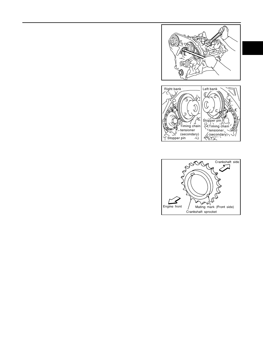
• Secure camshaft using wrench at the hexagonal portion to

tighten bolts.

d.

Pull stopper pins out from timing chain tensioners (secondary).

6.

Install tension guide.

7.

Install timing chain (primary) as follows:

a.

Install crankshaft sprocket.
• Make sure the mating marks on crankshaft sprocket face the

front of engine.

KBIA1698J

PBIC2110E

SEM929E

2009 Pathfinder

EM-74

< ON-VEHICLE REPAIR >

[VQ40DE]

TIMING CHAIN

b.

Install the primary timing chain.
• Water pump (G).
• Install primary timing chain so the mating mark punched (B) on

camshaft sprocket is aligned with the blue link (A) on the tim-
ing chain, while the mating mark notched (E) on the crankshaft
sprocket (D) is aligned with the copper link (F) on the timing
chain, as shown.

• When it is difficult to align mating marks (A) with (B) and (E)

with (F) of the primary timing chain with each sprocket, gradu-
ally turn the camshaft using a wrench on the hexagonal por-
tion to align it with the mating marks.

• During alignment, be careful to prevent dislocation of mating

mark alignments of the secondary timing chains.

8.

Install internal chain guide, slack guide and timing chain ten-
sioner (primary).

CAUTION:

WBIA0721E

PBIC2109E

2009 Pathfinder

TIMING CHAIN

EM-75

< ON-VEHICLE REPAIR >

[VQ40DE]

C

D

E

F

G

H

I

J

K

L

M

A

EM

N

P

O

Do not overtighten slack guide bolts. It is normal for a gap
to exist under the bolt seats when bolts are tightened to
specification.

• When installing timing chain tensioner (primary), push in plunger and keep it pressed in with stopper pin.
• Remove any dirt and foreign materials completely from the back and the mounting surfaces of timing

chain tensioner (primary).

• After installation, pull out stopper pin.

9.

Make sure again that the mating marks on camshaft sprockets and timing chain have not slipped out of
alignment.

10. Install new O-rings on rear timing chain case.

11. Install new front oil seal on front timing chain case.

• Apply new engine oil to both oil seal lip and dust seal lip.
• Install it so that each seal lip is oriented as shown. 

PBIC2633E

PBIC2548E

SEM715A

2009 Pathfinder

EM-76

< ON-VEHICLE REPAIR >

[VQ40DE]

TIMING CHAIN

• Press-fit oil seal until it becomes flush with front timing chain

case end face using suitable drift [outer diameter: 60 mm (2.36
in)].

• Make sure the garter spring is in position and seal lip is not

inverted.

12. Install water pump cover and chain tensioner cover to front timing chain case.

• Apply a continuous bead of liquid gasket using Tool to front

timing chain case as shown.

Use Genuine RTV Silicone Sealant or equivalent. Refer to

GI-26, "Recommended Chemical Products and Sealants"

.

13. Install front timing chain case as follows:

a.

Apply a continuous bead of liquid gasket using Tool to front tim-
ing chain case back side as shown.

Use Genuine RTV Silicone Sealant or equivalent. Refer to

GI-26, "Recommended Chemical Products and Sealants"

.

PBIC2911E

Tool number

: WS39930000 (

)

PBIC2912E

Tool number

: WS39930000 (

)

PBIC2913E

2009 Pathfinder

TIMING CHAIN

EM-77

< ON-VEHICLE REPAIR >

[VQ40DE]

C

D

E

F

G

H

I

J

K

L

M

A

EM

N

P

O

b.

Install new O-rings on rear timing chain case.

c.

Assemble front timing chain case as follows:

i.

Fit lower end of front timing chain case tightly onto top face of oil
pan (upper). From the fitting point, make entire front timing chain
case contact rear timing chain case completely.

ii.

Since front timing chain case is offset for difference of bolt holes,
tighten bolts temporarily while holding front timing chain case
from front and top as shown.

iii.

Same as the previous step, insert dowel pin while holding front
timing chain case from front and top completely.

d.

Tighten bolts to the specified torque in numerical order as
shown.

e.

After all bolts tightened, retighten them to the specified torque in
numerical order as shown.

PBIC2548E

PBIC1100E

PBIC2915E

Bolt position

Bolt diameter

1 - 5

: 10 mm (0.39 in)

6 – 25

: 6 mm (0.24 in)

Bolt position

Tightening specification

1 - 5

: 55.0 N·m (5.6 kg-m, 41 ft-lb)

6 – 25

: 12.7 N·m (1.3 kg-m, 9 ft-lb)

PBIC2908E

2009 Pathfinder

EM-78

< ON-VEHICLE REPAIR >

[VQ40DE]

TIMING CHAIN

14. Install two bolts in front of oil pan (upper) in numerical order as

shown.

15. Install right and left intake valve timing control covers as follows:

a.

Install new seal rings in shaft grooves.

b.

Apply a continuous bead of liquid gasket using Tool to intake
valve timing control covers as shown.

Use Genuine RTV Silicone Sealant or equivalent. Refer to

GI-26, "Recommended Chemical Products and Sealants"

.

c.

Install new collared O-rings in front timing chain case oil hole
(left and right sides).

d.

Being careful not to move seal ring from the installation groove, align dowel pins on front timing chain
case with the holes to install intake valve timing control covers.

e.

Tighten bolts in numerical order as shown.

16. Install crankshaft pulley as follows:

a.

Install crankshaft pulley, taking care not to damage front oil seal.
• When press-fitting crankshaft pulley with plastic hammer, tap on its center portion (not circumference).

b.

Tighten crankshaft pulley bolt in two steps.

Front oil pan bolt torque

: 22.0 N·m (2.2 kg-m, 16 ft-lb)

PBIC2907E

Tool number

: WS39930000 (

)

SBIA0492E

PBIC2631E

PBIC0918E

2009 Pathfinder

TIMING CHAIN

EM-79

< ON-VEHICLE REPAIR >

[VQ40DE]

C

D

E

F

G

H

I

J

K

L

M

A

EM

N

P

O

c.

Remove Tool. 

17. Rotate crankshaft pulley in normal direction (clockwise when viewed from front) to confirm it turns

smoothly.

18. Install oil pans (upper and lower). Refer to 

EM-35, "Removal and Installation"

.

19. Install rocker covers (right and left banks). Refer to 

EM-41, "Removal and Installation"

.

20. Installation of the remaining components is in the reverse order of removal after this step.

INSPECTION AFTER INSTALLATION

• Before starting the engine, check oil/fluid levels including engine coolant and engine oil. If the levels are

lower than required quantity, fill to the specified level. Refer to 

MA-12, "Fluids and Lubricants"

.

• Use procedure below to check for fuel leakage.
• Turn ignition switch ON (with engine stopped). With fuel pressure applied to the fuel piping, check for fuel

leakage at the connection points.

• Start engine. With engine speed increased, check again for fuel leakage at connection points.
• Run engine to check for unusual noise and vibration.

NOTE:
If hydraulic pressure inside timing chain tensioner drops after removal and installation, slack in the guide
may generate a pounding noise during and just after engine start. However, this is normal. Noise will stop
after hydraulic pressure rises.

• Warm up engine thoroughly to make sure there is no leakage of fuel, exhaust gas, or any oil/fluids including

engine oil and engine coolant.

• Bleed air from passages in lines and hoses, such as in cooling system.
• After cooling down the engine, again check oil/fluid levels including engine oil and engine coolant. Refill to

specified level if necessary.

• Summary of the inspection items:

* Transmission/transaxle/CVT fluid, power steering fluid, brake fluid, etc.

Step 1

: 44.1 N·m (4.5 kg-m, 33 ft-lb)

Step 2

:84

°

 - 90

°

 degrees clockwise

Tool number

:   —   (J-48761)

WBIA0580E

Item

Before starting engine

Engine running

After engine stopped

Engine coolant

Level

Leakage

Level

Engine oil

Level

Leakage

Level

Other oils and fluids*

Level

Leakage

Level

Fuel

Leakage

Leakage

Leakage

Exhaust gas

Leakage

2009 Pathfinder

EM-80

< ON-VEHICLE REPAIR >

[VQ40DE]

CAMSHAFT

CAMSHAFT

Exploded View

INFOID:0000000003939505

1.

Intake valve timing control solenoid 
valve (RH bank)

2.

Gasket

3.

Camshaft bracket (No. 2 to 4)

4.

Camshaft (EXH)

5.

Camshaft (INT)

6.

Camshaft bracket (No. 1)

7.

Dowel pin

8.

Valve lifter

9.

O-ring

10.

Timing chain tensioner (secondary) 
(RH bank)

11.

Spring

12. Plunger

13.

Timing chain tensioner (secondary) 
(LH bank)

14.

Cylinder head (RH bank)

15. Cylinder head (LH bank)

16. O-ring

17.

Camshaft position sensor (PHASE) 
(RH bank)

18.

Camshaft position sensor (PHASE) 
(LH bank)

19. Intake valve timing control solenoid 

valve (LH bank)

PBIC2930E

2009 Pathfinder


Content      ..     375      376      377      378     ..