Nissan Pathfinder (2009 year). Manual - part 309
EC-486
< ON-VEHICLE MAINTENANCE >
[VQ40DE]
EVAP LEAK CHECK
EVAP LEAK CHECK
How to Detect Fuel Vapor Leakage
INFOID:0000000004297673
CAUTION:
• Never use compressed air or a high pressure pump.
• Never exceed 4.12 kPa (0.042 kg/cm
2
, 0.6 psi) of pressure in EVAP system.
NOTE:
• Do not start engine.
• Improper installation of EVAP service port adapter to the EVAP service port may cause a leak.
WITH CONSULT-III
1.
Attach the EVAP service port adapter securely to the EVAP service port.
2.
Also attach the pressure pump and hose to the EVAP service port adapter.
3.
Turn ignition switch ON.
4.
Select the “EVAP SYSTEM CLOSE” of “WORK SUPPORT MODE” with CONSULT-III.
5.
Touch “START”. A bar graph (Pressure indicating display) will appear on the screen.
6.
Apply positive pressure to the EVAP system until the pressure indicator reaches the middle of the bar
graph.
7.
Remove EVAP service port adapter and hose with pressure pump.
8.
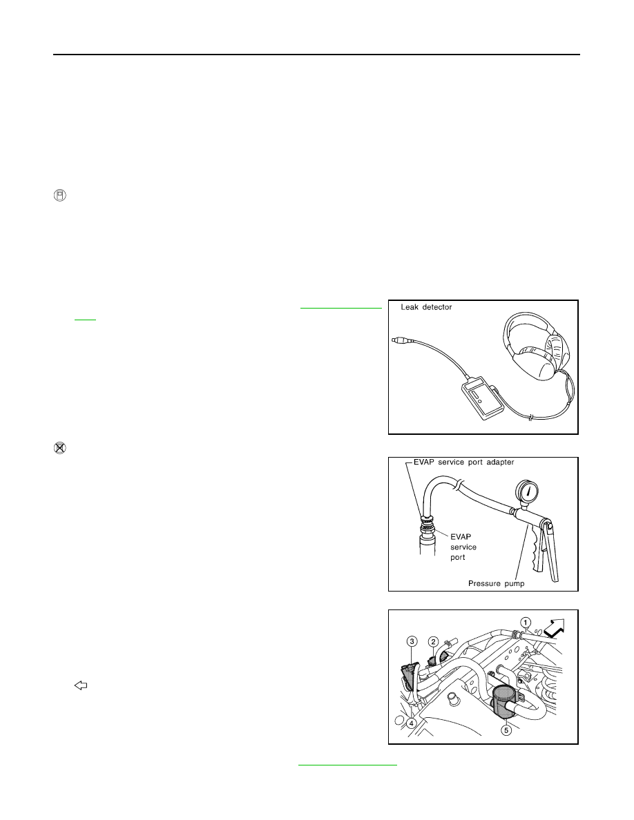
Locate the leak using a leak detector. Refer to
WITHOUT CONSULT-III
1.
Attach the EVAP service port adapter securely to the EVAP ser-
vice port.
2.
Also attach the pressure pump with pressure gauge to the EVAP
service port adapter.
3.
Apply battery voltage between the terminals of EVAP canister
vent control valve (3) to make a closed EVAP system.
-
Fuel filler pipe (top of frame view) (1)
-
EVAP control system pressure sensor (2)
-
EVAP ccanister (4)
-
Drain filter (5)
-
: Vehicle front
4.
To locate the leak, deliver positive pressure to the EVAP system
until pressure gauge points reach 1.38 to 2.76 kPa (0.014 to
0.028 kg/cm
2
, 0.2 to 0.4 psi).
5.
Remove EVAP service port adapter and hose with pressure
pump.
6.
Locate the leak using a leak detector. Refer to
SEF200U
SEF462UA
AWBIA0134ZZ
2009 Pathfinder