Nissan Pathfinder (2009 year). Manual - part 276
EC-222
< COMPONENT DIAGNOSIS >
[VQ40DE]
P0420, P0430 THREE WAY CATALYST FUNCTION
15. Confirm that the 1st trip DTC is not detected.
If the 1st trip DTC is detected, go to
.
Overall Function Check
INFOID:0000000004297412
Use this procedure to check the overall function of the three way catalyst (manifold). During this check, a 1st
trip DTC might not be confirmed.
WITH GST
1.
Start engine and warm it up to the normal operating temperature.
2.
Turn ignition switch OFF and wait at least 10 seconds.
3.
Turn ignition switch ON.
4.
Turn ignition switch OFF and wait at least 10 seconds.
5.
Start engine and keep the engine speed between 3,500 and 4,000 rpm for at least 1 minute under no load.
6.
Let engine idle for 1 minute.
7.
Open engine hood.
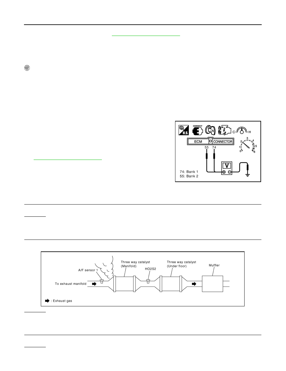
8.
Set voltmeter probe between ECM terminals 74 [HO2S2 (bank
1) signal], 55 [HO2S2 (bank 2) signal] and ground.
9.
Keep engine speed at 2,500 rpm constant under no load.
10. Make sure that the voltage does not vary for more than 5 sec-
onds.
If the voltage fluctuation cycle takes less than 5 seconds, go to
• 1 cycle: 0.6 - 1.0
→
0 - 0.3
→
0.6 - 1.0
Diagnosis Procedure
INFOID:0000000004297413
1.
CHECK EXHAUST SYSTEM
Visually check exhaust tubes and muffler for dent.
OK or NG
OK
>> GO TO 2.
NG
>> Repair or replace.
2.
CHECK EXHAUST GAS LEAK
1.
Start engine and run it at idle.
2.
Listen for an exhaust gas leak before the three way catalyst (manifold).
OK or NG
OK
>> GO TO 3.
NG
>> Repair or replace.
3.
CHECK INTAKE AIR LEAK
Listen for an intake air leak after the mass air flow sensor.
OK or NG
OK
>> GO TO 4.
PBIB1108E
PBIB1216E
2009 Pathfinder