Nissan Pathfinder (2009 year). Manual - part 271
EC-182
< COMPONENT DIAGNOSIS >
[VQ40DE]
P0171, P0174 FUEL INJECTION SYSTEM FUNCTION
CAUTION:
Always drive vehicle at a safe speed.
9.
If it is difficult to start engine at step 6, the fuel injection system has a malfunction, too.
10. Crank engine while depressing accelerator pedal. If engine starts, go to
. If
engine does not start, check exhaust and intake air leak visually.
WITH GST
1.
Start engine and warm it up to normal operating temperature.
2.
Turn ignition switch OFF and wait at least 10 seconds.
3.
Turn ignition switch ON.
4.
Turn ignition switch OFF and wait at least 10 seconds.
5.
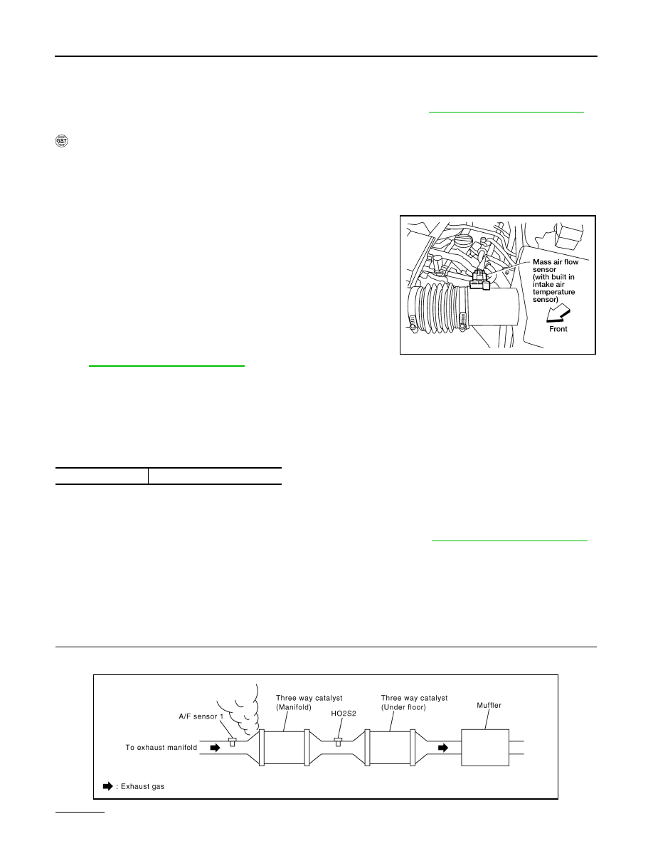
Disconnect mass air flow sensor harness connector.
6.
Restart engine and let it idle for at least 5 seconds.
7.
Stop engine and reconnect mass air flow sensor harness con-
nector.
8.
Select Service $03 with GST. Make sure DTC P0102 is
detected.
9.
Select Service $04 with GST and erase the DTC P0102.
10. Start engine again and let it idle for at least 5 minutes.
11. Select Service $07 with GST. The 1st trip DTC P0171 or P0174
should be detected at this stage, if a malfunction exists. If so, go
to
.
NOTE:
If 1st trip DTC is not detected during above procedure, performing the following procedure is advised.
a.
Turn ignition switch OFF and wait at least 10 seconds.
b.
Start engine.
c.
Maintain the following conditions for at least 10 consecutive minutes. Hold the accelerator pedal as steady
as possible.
CAUTION:
Always drive vehicle at a safe speed.
12. If it is difficult to start engine at step 8, the fuel injection system has a malfunction.
13. Crank engine while depressing accelerator pedal. If engine starts, go to
If engine does not start, check exhaust and intake air leak visually.
NOTE:
WHen depressing accelerator pedal three-fourths (3/4) or more, the control system does not start the engine.
Do not depress accelerator pedal too much.
Diagnosis Procedure
INFOID:0000000004351988
1.
CHECK EXHAUST GAS LEAK
1.
Start engine and run it at idle.
2.
Listen for an exhaust gas leak before three way catalyst (manifold).
OK or NG
VHCL SPEED SE
50 - 120 km/h (31 - 75 mph)
BBIA0541E
PBIB1216E
2009 Pathfinder