Nissan Pathfinder (2009 year). Manual - part 215
DLN-202
< COMPONENT DIAGNOSIS >
[TRANSFER: TX15B]
P1801, P1811 POWER SUPPLY CIRCUIT FOR TRANSFER CONTROL UNIT
COMPONENT DIAGNOSIS
P1801, P1811 POWER SUPPLY CIRCUIT FOR TRANSFER CONTROL
UNIT
Description
INFOID:0000000003937323
The transfer control unit controls the transfer control device which controls shifts between 4H and 4LO and
between 2WD and 4WD. When the vehicle battery is removed, the power supply to the transfer control unit is
interupted, and self-diagnosis memory function is suspended. These DTC's may also set when the power
supply voltage for the transfer control unit is abnormally low while driving.
DTC Logic
INFOID:0000000003937324
DTC DETECTION LOGIC
DTC CONFIRMATION PROCEDURE
1.
DTC CONFIRMATION PROCEDURE
1.
Turn ignition switch ON.
2.
Perform self-diagnosis.
Are DTC's “P1801 or P1811 detected?
YES
>> Perform diagnosis procedure. Refer to
DLN-202, "Diagnosis Procedure"
.
NO
>> Inspection End.
Diagnosis Procedure
INFOID:0000000003937325
1.
CHECK POWER SUPPLY
1.
Turn ignition switch “OFF”. (Stay for at least 5 seconds.)
2.
Disconnect transfer control unit harness connector.
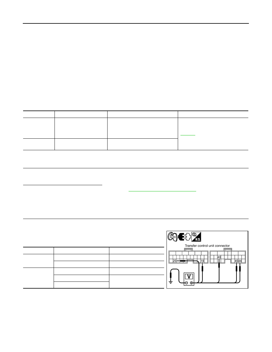
3.
Check voltage between transfer control unit harness connector
terminals and ground.
DTC
CONSULT-III
Diagnostic item is detected when...
Reference
[P1801]
*INITIAL START*
Due to removal of battery which cuts off
power supply to transfer control unit,
self-diagnosis memory function is sus-
pended.
[P1811]
BATTERY VOLTAGE
Power supply voltage for transfer control
unit is abnormally low while driving.
Connector
Terminal
Voltage (Approx.)
M165
19 - Ground
Battery voltage
25 - Ground
0V
M166
40 - Ground
Battery voltage
44 - Ground
0V
45 - Ground
SDIA3360E
2009 Pathfinder