Nissan Pathfinder (2009 year). Manual - part 189


  Index      Manuals     Nissan Pathfinder (2009 year) - Service and Repair Manual


Search            copyright infringement  


Content      ..     187      188      189      190     ..


Nissan Pathfinder (2009 year). Manual - part 189


DOOR

DLK-321

< ON-VEHICLE REPAIR >

[WITHOUT INTELLIGENT KEY SYSTEM]

C

D

E

F

G

H

I

J

L

M

A

B

DLK

N

O

P

REAR DOOR

1.

Remove the door finisher. Refer to 

INT-14, "Removal and Installation"

.

2.

Remove the inner seal. 

3.

Remove the rear door glass and regulator. Refer to 

GW-19, "Rear Door Glass Regulator"

.

4.

Remove the door harness.

5.

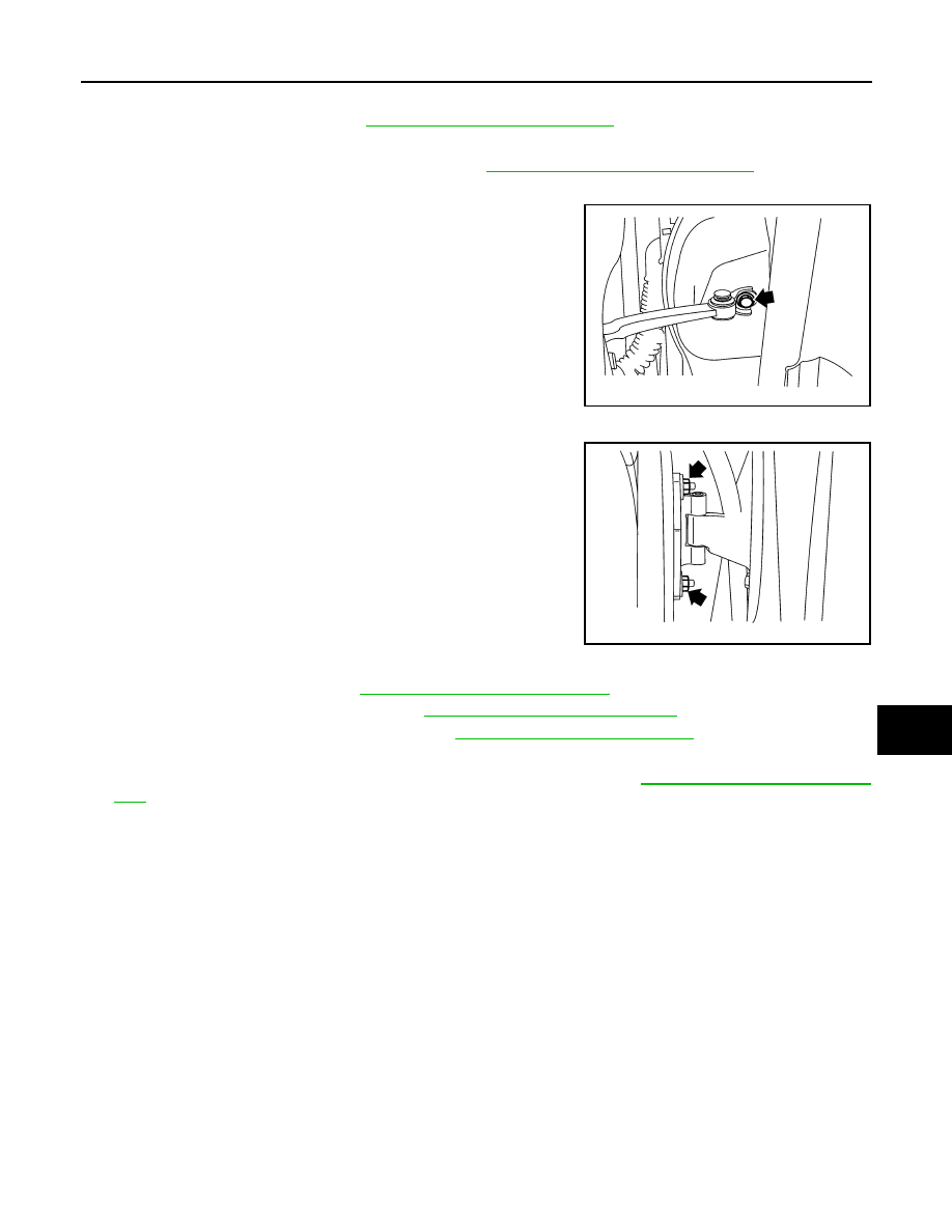
Remove the check link bolt from the hinge pillar.

6.

Remove the door-side hinge nuts, and remove the door assembly.

Installation is in the reverse order of removal.

BACK DOOR

1.

Remove the glass hatch. Refer to 

GW-24, "Removal and Installation"

.

2.

Remove the license lamp finisher. Refer to 

EXT-21, "Removal and Installation"

.

3.

Remove the back door lock assembly. Refer to 

DLK-327, "Component Structure"

.

4.

Remove the back door wire harness.

5.

Remove the rear washer nozzle and hose from the back door. Refer to 

WW-83, "Removal and Installa-

tion"

CAUTION:

Two technicians should be used to avoid damaging the back door during removal.

6.

Support the back door.

7.

Remove the back door stays.

Check link to hinge pillar 
bolt

14.7 N·m (1.5 kg-m, 11 ft-lb)

LIIA1726E

Door hinge nuts

24.5 N·m (2.5 kg-m, 18 ft-lb)

LIIA1727E

2009 Pathfinder

DLK-322

< ON-VEHICLE REPAIR >

[WITHOUT INTELLIGENT KEY SYSTEM]

DOOR

8.

Remove the door side nuts and the back door assembly.

Installation is in the reverse order of removal.
• Align the back door. Refer to 

DLK-318, "Fitting Adjustment"

.

WIIA1056E

2009 Pathfinder

FRONT DOOR LOCK

DLK-323

< ON-VEHICLE REPAIR >

[WITHOUT INTELLIGENT KEY SYSTEM]

C

D

E

F

G

H

I

J

L

M

A

B

DLK

N

O

P

FRONT DOOR LOCK

Component Structure

INFOID:0000000003938406

Removal and Installation

INFOID:0000000003938407

REMOVAL

1.

Remove the front door window regulator. Refer to 

GW-15, "Front Door Glass Regulator"

.

2.

Remove door side grommet, and remove door key cylinder
assembly (driver side) or outside handle escutcheon (passenger
side) bolts (TORX T30) from grommet hole.

3.

While pulling the outside handle (1), remove door key cylinder
assembly or escutcheon (2).

1.

Grommet

2.

Front door striker

3.

Door lock assembly

4.

Outside handle cable

5.

Inside handle assembly

6.

Inside handle cable

7.

Door lock cable

8.

Key cylinder rod (Driver side only)

9.

Door key cylinder

10. Outside handle bracket

11.

Front gasket

12. Outside handle

13. Door key cylinder assembly (Driver 

side) Outside handle escutcheon 
(Passenger side)

14. Rear gasket

Vehicle front

WIIA0736E

PIIA3553E

ALKIA0956ZZ

2009 Pathfinder

DLK-324

< ON-VEHICLE REPAIR >

[WITHOUT INTELLIGENT KEY SYSTEM]

FRONT DOOR LOCK

4.

If equipped, separate the door key cylinder rod from the door key cylinder assembly.

5.

While pulling outside handle (1), slide toward rear of vehicle (2)
to remove outside handle.

6.

Remove the front gasket (1) and rear gasket (2).

7.

Remove the TORX bolts (T30), remove the door lock assembly.

8.

While pulling outside handle bracket, slide toward rear of vehicle
to remove outside handle bracket and door lock assembly as
shown.

9.

Disconnect the door lock actuator electrical connector.

ALKIA0957ZZ

ALKIA0924ZZ

PIIA1090E

PIIA3558E

2009 Pathfinder

FRONT DOOR LOCK

DLK-325

< ON-VEHICLE REPAIR >

[WITHOUT INTELLIGENT KEY SYSTEM]

C

D

E

F

G

H

I

J

L

M

A

B

DLK

N

O

P

10. Separate the outside handle cable connection from the outside

handle bracket.

INSTALLATION

Installation is in the reverse order of removal.

CAUTION:

To install the key cylinder rod, be sure to rotate the key cylinder rod holder until a click is felt.

Disassembly and Assembly

INFOID:0000000003938408

DOOR KEY CYLINDER ASSEMBLY

Release the key cylinder escutcheon pawls to remove the door key cylinder.

PIIA5059E

1.

Door key cylinder assembly

2.

Door key cylinder escutcheon

3.

Door key cylinder

Pawl

WIIA1057E

2009 Pathfinder

DLK-326

< ON-VEHICLE REPAIR >

[WITHOUT INTELLIGENT KEY SYSTEM]

REAR DOOR LOCK

REAR DOOR LOCK

Component Structure

INFOID:0000000003938409

Removal and Installation

INFOID:0000000003938410

REMOVAL

1.

Remove the rear door window regulator. Refer to 

GW-19, "Rear Door Glass Regulator"

.

2.

Remove door grommets, and remove outside handle nuts from the hole.

3.

Remove outside handle.

4.

Disconnect the outside handle cable connection.

5.

Remove the inside door handle.

6.

Disconnect the door lock and inside door handle cables from the inside door handle.

7.

Disconnect the door lock actuator connector and remove the assembly.

INSTALLATION

Installation is in the reverse order of removal.

1.

Outside door handle

2.

Rear door striker

3.

Rear door lock assembly

4.

Outside door handle cable

5.

Inside door handle cable

6.

Inside door handle assembly

7.

Door lock cable

Vehicle front

WIIA0737E

2009 Pathfinder

BACK DOOR LOCK

DLK-327

< ON-VEHICLE REPAIR >

[WITHOUT INTELLIGENT KEY SYSTEM]

C

D

E

F

G

H

I

J

L

M

A

B

DLK

N

O

P

BACK DOOR LOCK

Component Structure

INFOID:0000000003938411

1.

Glass hatch latch assembly

2.

Back door control assembly

3.

Back door striker

4.

Back door latch assembly

5.

Back door release button

6.

Back door finisher

7.

Glass hatch release handle

8.

Glass latch release cable 

9.

Glass hatch release cable

Front

AWKIA1438GB

2009 Pathfinder

DLN-1

TRANSMISSION & DRIVELINE

C

E

F

G

H

I

J

K

L

M

SECTION 

DLN

A

B

DLN

N

O

P

CONTENTS

DRIVELINE

TRANSFER: ATX14B

BASIC INSPECTION  ....................................

8

DIAGNOSIS AND REPAIR WORKFLOW  ..........

8

Work Flow  .................................................................

8

Preliminary Check  .....................................................

9

FUNCTION DIAGNOSIS ..............................

12

4WD SYSTEM  ....................................................

12

System Diagram ......................................................

12

System Description  .................................................

13

Component Parts Location ......................................

18

CAN Communication ...............................................

19

Cross-Sectional View  ..............................................

19

Power Transfer ........................................................

19

DIAGNOSIS SYSTEM (TRANSFER CON-
TROL UNIT) ........................................................

22

CONSULT-III Function (ALL MODE AWD/4WD) ....

22

NOISE, VIBRATION AND HARSHNESS 
(NVH) TROUBLESHOOTING  ............................

26

NVH Troubleshooting Chart  ....................................

26

COMPONENT DIAGNOSIS  .........................

27

P1811 POWER SUPPLY CIRCUIT FOR 
TRANSFER CONTROL UNIT  ............................

27

Description ..............................................................

27

DTC Logic  ...............................................................

27

Diagnosis Procedure ...............................................

27

Component Inspection  ............................................

28

P1802 – P1804, P1809 TRANSFER CON-
TROL UNIT .........................................................

29

Description ..............................................................

29

DTC Logic  ...............................................................

29

Diagnosis Procedure ...............................................

29

P1807 VEHICLE SPEED SENSOR (A/T)  ..........

31

Description ...............................................................

31

DTC Logic ................................................................

31

Diagnosis Procedure  ...............................................

31

P1808 VEHICLE SPEED SENSOR (ABS)  .......

32

Description ...............................................................

32

DTC Logic ................................................................

32

Diagnosis Procedure  ...............................................

32

P1810 NEUTRAL-4LO SWITCH .......................

33

Description ...............................................................

33

DTC Logic ................................................................

33

Diagnosis Procedure  ...............................................

33

Component Inspection .............................................

35

P1813 4WD SHIFT SWITCH .............................

36

Description ...............................................................

36

DTC Logic ................................................................

36

Diagnosis Procedure  ...............................................

36

Component Inspection .............................................

38

P1814 WAIT DETECTION SWITCH  .................

40

Description ...............................................................

40

DTC Logic ................................................................

40

Diagnosis Procedure  ...............................................

40

Component Inspection .............................................

42

P1816 PNP SWITCH .........................................

43

Description ...............................................................

43

DTC Logic ................................................................

43

Diagnosis Procedure  ...............................................

43

P1817 ACTUATOR MOTOR .............................

44

Description ...............................................................

44

DTC Logic ................................................................

44

Diagnosis Procedure  ...............................................

44

Component Inspection .............................................

48

P1818 ACTUATOR POSITION SWITCH  ..........

50

Description ...............................................................

50

DTC Logic ................................................................

50

Diagnosis Procedure  ...............................................

50

2009 Pathfinder


Content      ..     187      188      189      190     ..