Nissan Pathfinder (2009 year). Manual - part 82


  Index      Manuals     Nissan Pathfinder (2009 year) - Service and Repair Manual


Search            copyright infringement  


Content      ..     80      81      82      83     ..


Nissan Pathfinder (2009 year). Manual - part 82


AV-468

< ON-VEHICLE REPAIR >

[BOSE AUDIO WITH NAVIGATION]

STEERING SWITCH

STEERING SWITCH

Removal and Installation

INFOID:0000000003939299

Removal and Installation

REMOVAL

1.

Remove the driver air bag module. Refer to 

SR-5, "Removal and Installation"

.

2.

Remove the steering wheel. Refer to 

ST-12, "On-Vehicle Inspection and Service"

.

3.

Remove the steering wheel rear cover.

4.

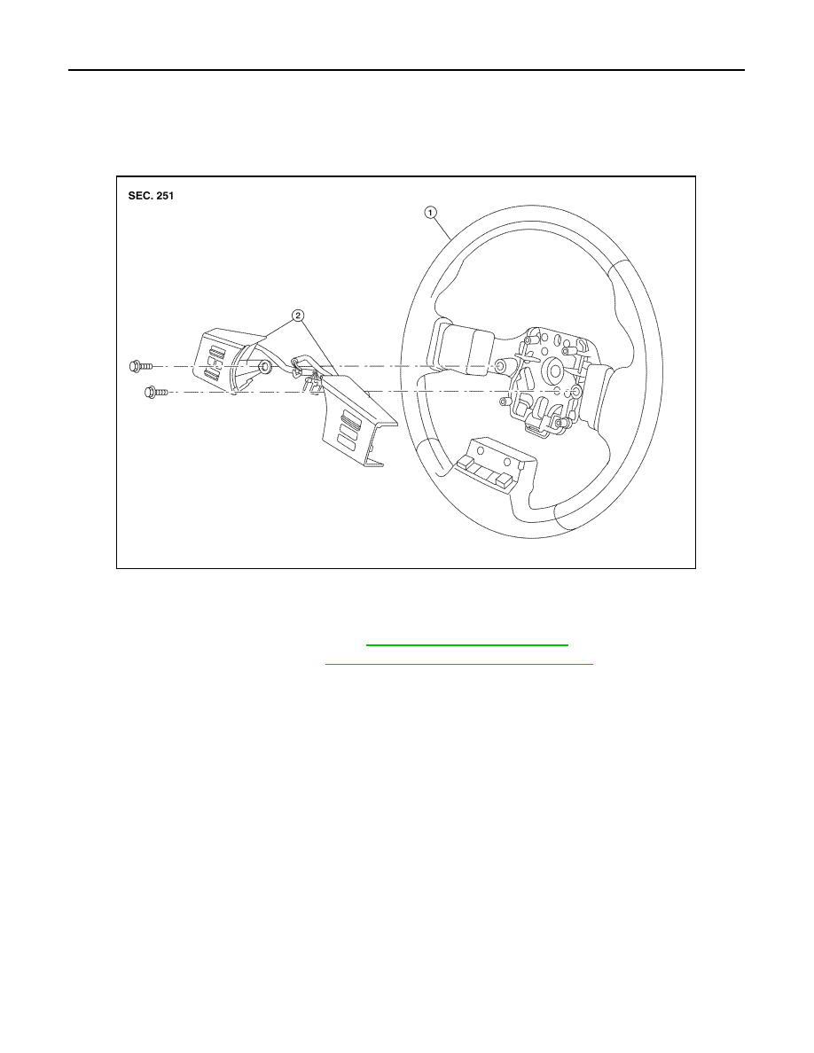
Remove the steering wheel audio control switch assembly screws.

5.

Disconnect the steering wheel audio control switches connector and remove the steering wheel audio
control switches.

INSTALLATION

Installation is in the reverse order of removal.

1. Steering wheel

2.

Steering wheel audio control switches

ALNIA0357ZZ

2009 Pathfinder

AV

MICROPHONE

AV-469

< ON-VEHICLE REPAIR >

[BOSE AUDIO WITH NAVIGATION]

C

D

E

F

G

H

I

J

K

L

M

B

A

O

P

MICROPHONE

Removal and Installation

INFOID:0000000003939300

REMOVAL

1.

Remove the front roof console finisher. Refer to 

INT-20, "Removal and Installation"

.

2.

Detach the Bluetooth microphone (1) from the front console fin-
isher tabs (A).

3.

Detach the Bluetooth microphone connector (B) and remove the
Bluetooth microphone (1).

INSTALLATION

Installation is in the reverse order of removal.

ALNIA0379ZZ

2009 Pathfinder

AV-470

< ON-VEHICLE REPAIR >

[BOSE AUDIO WITH NAVIGATION]

REAR VIEW CAMERA

REAR VIEW CAMERA

Removal and Installation

INFOID:0000000003939302

Rear View Camera

REMOVAL

1.

Disconnect the battery negative terminal.

2.

Remove the back door lower finisher. Refer to 

INT-25, "Removal and Installation"

.

3.

Disconnect the rear view camera connector.

4.

Detach the rear view camera harness clip.

5.

Detach the rear view camera to release, then pull out to remove the rear view camera while feeding the
rear view camera harness and connector through the back door.

INSTALLATION

Installation is in the reverse order of removal.

1.

Rear view camera

A.

Rear view camera connector

B.

Rear view camera harness clip

ALNIA1182ZZ

2009 Pathfinder

AV

REAR VIEW CAMERA CONTROL UNIT

AV-471

< ON-VEHICLE REPAIR >

[BOSE AUDIO WITH NAVIGATION]

C

D

E

F

G

H

I

J

K

L

M

B

A

O

P

REAR VIEW CAMERA CONTROL UNIT

Removal and Installation

INFOID:0000000003939303

REMOVAL

1.

Disconnect the battery negative terminal.

2.

Remove the luggage side lower finisher RH. Refer to 

INT-23, "Removal and Installation"

.

3.

Remove the rear HVAC duct tube (C103) fastener and remove the HVAC duct tube.

4.

Remove the rear view camera control unit screws (A), discon-
nect the rear view camera control unit connector (B) and remove
the rear view camera control unit (1).

INSTALLATION

Installation is in the reverse order of removal.

ALNIA0377ZZ

2009 Pathfinder

BCS

BCS-1

ELECTRICAL & POWER CONTROL

C

D

E

F

G

H

I

J

K

L

B

SECTION 

BCS

A

O

P

N

CONTENTS

BODY CONTROL SYSTEM

BASIC INSPECTION  ....................................

3

INSPECTION AND ADJUSTMENT .....................

3

ADDITIONAL SERVICE WHEN REPLACING 
CONTROL UNIT  ........................................................
..

3

ADDITIONAL SERVICE WHEN REPLACING 
CONTROL UNIT : Description  ................................
..

3

ADDITIONAL SERVICE WHEN REPLACING 
CONTROL UNIT : Special Repair Requirement  .....
..

3

CONFIGURATION .......................................................

3

CONFIGURATION : Description  ...............................

3

CONFIGURATION : Special Repair Requirement 

......

4

FUNCTION DIAGNOSIS ...............................

5

BODY CONTROL SYSTEM ................................

5

System Description  ...................................................

5

Component Parts Location ........................................

6

COMBINATION SWITCH READING SYSTEM 

.....

7

System Diagram ........................................................

7

System Description  ...................................................

7

Component Parts Location ......................................

10

SIGNAL BUFFER SYSTEM  ...............................

12

System Diagram ......................................................

12

System Description  .................................................

12

POWER CONSUMPTION CONTROL SYS-
TEM ....................................................................

13

System Diagram ......................................................

13

System Description  .................................................

13

Component Parts Location ......................................

15

DIAGNOSIS SYSTEM (BCM)  ............................

16

COMMON ITEM  .........................................................

16

COMMON ITEM : CONSULT-III Function (BCM - 
COMMON ITEM) .....................................................

16

BCM ...........................................................................

16

BCM : CONSULT-III Function (BCM - BCM) ...........

17

DOOR LOCK ..............................................................

17

DOOR LOCK : CONSULT-III Function (BCM - 
DOOR LOCK) ..........................................................

17

REAR WINDOW DEFOGGER  ...................................

18

REAR WINDOW DEFOGGER : CONSULT-III 
Function (BCM - REAR DEFOGGER) .....................

18

BUZZER .....................................................................

18

BUZZER : CONSULT-III Function (BCM - BUZZ-
ER) ..........................................................................

18

INT LAMP ...................................................................

18

INT LAMP : CONSULT-III Function (BCM - INT 
LAMP) ......................................................................

19

MULTIREMOTE ENT  .................................................

20

MULTIREMOTE ENT : CONSULT-III Function 
(BCM - MULTIREMOTE ENT) .................................

20

HEADLAMP ...............................................................

22

HEADLAMP : CONSULT-III Function (BCM - 
HEAD LAMP) ...........................................................

22

WIPER ........................................................................

23

WIPER : CONSULT-III Function (BCM - WIPER) ....

23

FLASHER ...................................................................

24

FLASHER : CONSULT-III Function (BCM - 
FLASHER) ...............................................................

24

AIR CONDITIONER  ...................................................

25

AIR CONDITIONER : CONSULT-III Function 
(BCM - AIR CONDITIONER) ...................................

25

INTELLIGENT KEY ....................................................

25

INTELLIGENT KEY : CONSULT-III Function 
(BCM - INTELLIGENT KEY) ....................................

25

COMB SW ..................................................................

25

2009 Pathfinder

BCS-2

COMB SW : CONSULT-III Function (BCM - 
COMB SW)  ............................................................
.

25

IMMU .........................................................................

26

IMMU : CONSULT-III Function (BCM - IMMU) .......

26

BATTERY SAVER  ....................................................

27

BATTERY SAVER : CONSULT-III Function (BCM 
- BATTERY SAVER)  .............................................
.

27

TRUNK ......................................................................

27

TRUNK : CONSULT-III Function (BCM - TRUNK) ...

27

RETAINED PWR  .......................................................

28

RETAINED PWR : CONSULT-III Function (BCM - 
RETAINED PWR)  ..................................................
.

28

SIGNAL BUFFER ......................................................

28

SIGNAL BUFFER : CONSULT-III Function (BCM 
- SIGNAL BUFFER) ...............................................
.

28

AIR PRESSURE MONITOR ......................................

29

AIR PRESSURE MONITOR : Diagnosis Descrip-
tion .........................................................................
.

29

AIR PRESSURE MONITOR : CONSULT-III Func-
tion .........................................................................
.

30

THEFT ALM  ..............................................................

31

THEFT ALM : CONSULT-III Function (BCM - 
THEFT ALM)  .........................................................
.

31

COMPONENT DIAGNOSIS  ........................

33

U1000 CAN COMM CIRCUIT  ............................

33

Description ..............................................................

33

DTC Logic ...............................................................

33

Diagnosis Procedure  ..............................................

33

U1010 CONTROL UNIT (CAN)  .........................

34

DTC Logic ...............................................................

34

Diagnosis Procedure  ..............................................

34

Special Repair Requirement ...................................

34

POWER SUPPLY AND GROUND CIRCUIT  .....

35

Diagnosis Procedure  ..............................................

35

COMBINATION SWITCH INPUT CIRCUIT  .......

36

Diagnosis Procedure ...............................................

36

Special Repair Requirement  ...................................

37

COMBINATION SWITCH OUTPUT CIRCUIT ...

38

Diagnosis Procedure ...............................................

38

Special Repair Requirement  ...................................

38

COMBINATION SWITCH  ..................................

39

Description ..............................................................

39

Diagnosis Procedure ...............................................

39

ECU DIAGNOSIS  .......................................

41

BCM (BODY CONTROL MODULE)  ..................

41

Reference Value  .....................................................

41

Terminal Layout  ......................................................

44

Physical Values .......................................................

44

Wiring Diagram  .......................................................

50

Fail Safe .................................................................

53

DTC Inspection Priority Chart ...............................

54

DTC Index ..............................................................

54

SYMPTOM DIAGNOSIS  ............................

56

COMBINATION SWITCH SYSTEM SYMP-
TOMS .................................................................

56

Symptom Table .......................................................

56

PRECAUTION ............................................

57

PRECAUTIONS  .................................................

57

Precaution for Supplemental Restraint System 
(SRS) "AIR BAG" and "SEAT BELT PRE-TEN-
SIONER" .................................................................

57

Precaution Necessary for Steering Wheel Rota-
tion After Battery Disconnect  ..................................

57

ON-VEHICLE REPAIR  ...............................

59

BCM (BODY CONTROL MODULE)  ..................

59

Removal and Installation .........................................

59

2009 Pathfinder

BCS

INSPECTION AND ADJUSTMENT

BCS-3

< BASIC INSPECTION >

C

D

E

F

G

H

I

J

K

L

B

A

O

P

N

BASIC INSPECTION

INSPECTION AND ADJUSTMENT

ADDITIONAL SERVICE WHEN REPLACING CONTROL UNIT

ADDITIONAL SERVICE WHEN REPLACING CONTROL UNIT : Description

INFOID:0000000003935242

When replacing BCM, save or print current vehicle specification with CONSULT-III configuration before
replacement.
Configuration has three functions as follows
• READ CONFIGURATION is the function to read (extract) vehicle configuration of current BCM.
• WRITE CONFIGURATION - Manual selection is the function to select and write vehicle configuration on

BCM manually.

• WRITE CONFIGURATION - Config file is the function to write vehicle configuration with the data extracted

from current BCM.

CAUTION:

• When replacing BCM, you must perform WRITE CONFIGURATION with CONSULT-III.
• Complete the procedure of WRITE CONFIGURATION in order.
• If you set incorrect WRITE CONFIGURATION, incidents will occur.
• Configuration is different for each vehicle model. Confirm configuration of each vehicle model.

ADDITIONAL SERVICE WHEN REPLACING CONTROL UNIT : Special Repair Re-
quirement

INFOID:0000000003935243

1.

 SAVING VEHICLE SPECIFICATION

Perform “READ CONFIGURATION” with CONSULT-III to save or print current vehicle specification.

>> GO TO 2

2.

 REPLACE BCM

Replace BCM. Refer to 

BCS-59, "Removal and Installation"

.

>> GO TO 3

3.

 WRITING VEHICLE SPECIFICATION

Perform “WRITE CONFIGURATION - Config file” or “WRITE CONFIGURATION - Manual selection” with
CONSULT-III to write vehicle specification. Refer to 

BCS-3, "ADDITIONAL SERVICE WHEN REPLACING

CONTROL UNIT : Special Repair Requirement"

.

>> GO TO 4

4.

 INITIALIZE BCM (NATS)

Perform BCM initialization. (NATS)

>> Work End.

CONFIGURATION

CONFIGURATION : Description

INFOID:0000000003935244

Vehicle specification needs to be written with CONSULT-III because it is not written after replacing BCM.
Configuration has three functions as follows
• READ CONFIGURATION is the function to read (extract) vehicle configuration of current BCM.
• WRITE CONFIGURATION - Manual selection is the function to select and write vehicle configuration on

BCM manually.

• WRITE CONFIGURATION - Config file is the function to write vehicle configuration with the data extracted

from current BCM.

CAUTION:

2009 Pathfinder

BCS-4

< BASIC INSPECTION >

INSPECTION AND ADJUSTMENT

• When replacing BCM, you must perform WRITE CONFIGURATION with CONSULT-III.
• Complete the procedure of WRITE CONFIGURATION in order.
• If you set incorrect WRITE CONFIGURATION, incidents will occur.
• Configuration is different for each vehicle model. Confirm configuration of each vehicle model.

CONFIGURATION : Special Repair Requirement

INFOID:0000000003935245

1.

 WRITING VEHICLE SPECIFICATION

Perform “WRITE CONFIGURATION” with CONSULT-III.

When writing saved data>>GO TO 2
When writing manually>>GO TO 3

2.

 PERFORM “WRITE CONFIGURATION - CONFIG FILE”

Perform “WRITE CONFIGURATION - Config file” with CONSULT-III.

>> Work End.

3.

 PERFORM “WRITE CONFIGURATION - MANUAL SELECTION”

For “WRITE CONFIGURATION - Manual selection”, using the following flow chart, identify the correct model
and configuration list.
Confirm and/or change setting value for each item according to the configuration list.
Depending on CONSULT-III software version being used, some or all of the write configuration items shown in
the following configuration lists may be displayed. If an item does not display on the CONSULT-III “WRITE
CONFIGURATION - Manual selection” screen, then it is an auto setting item and it cannot be manually set or
changed.

NOTE:
Confirm vehicle model. Refer to 

GI-32, "Model Variation"

.

>> Work End.

MANUAL SETTING ITEM

Items

Setting value

KEYLESS ENTRY

WITH

WITHOUT

I-KEY

WITH

WITHOUT

AUTO LIGHT

WITH

WITHOUT

DTRL

WITH

WITHOUT

SPEED SNS WIP

WITH

WITHOUT

THEFT ALARM

WITH

WITHOUT

2009 Pathfinder


Content      ..     80      81      82      83     ..