Nissan Pathfinder (2009 year). Manual - part 70
AV-372
< COMPONENT DIAGNOSIS >
[BOSE AUDIO WITH NAVIGATION]
POWER SUPPLY AND GROUND CIRCUIT
3.
Check voltage between rear view camera harness connector
D551 and ground.
Is voltage reading approximately 6 volts?
YES
>> GO TO 4
NO
>> GO TO 2
2.
CHECK POWER SUPPLY CIRCUIT (CONTINUITY)
1.
Turn ignition switch OFF.
2.
Disconnect rear view camera and rear view camera control unit connectors.
3.
Check continuity between rear view camera harness connector
D551 (A) terminal 1 and rear view camera control unit harness
connector B176 (B) terminal 8.
4.
Check continuity between rear view camera harness connector
D551 (A) terminal 1 and ground.
Are continuity results as specified?
YES
>> GO TO 3
NO
>> Repair harness or connector.
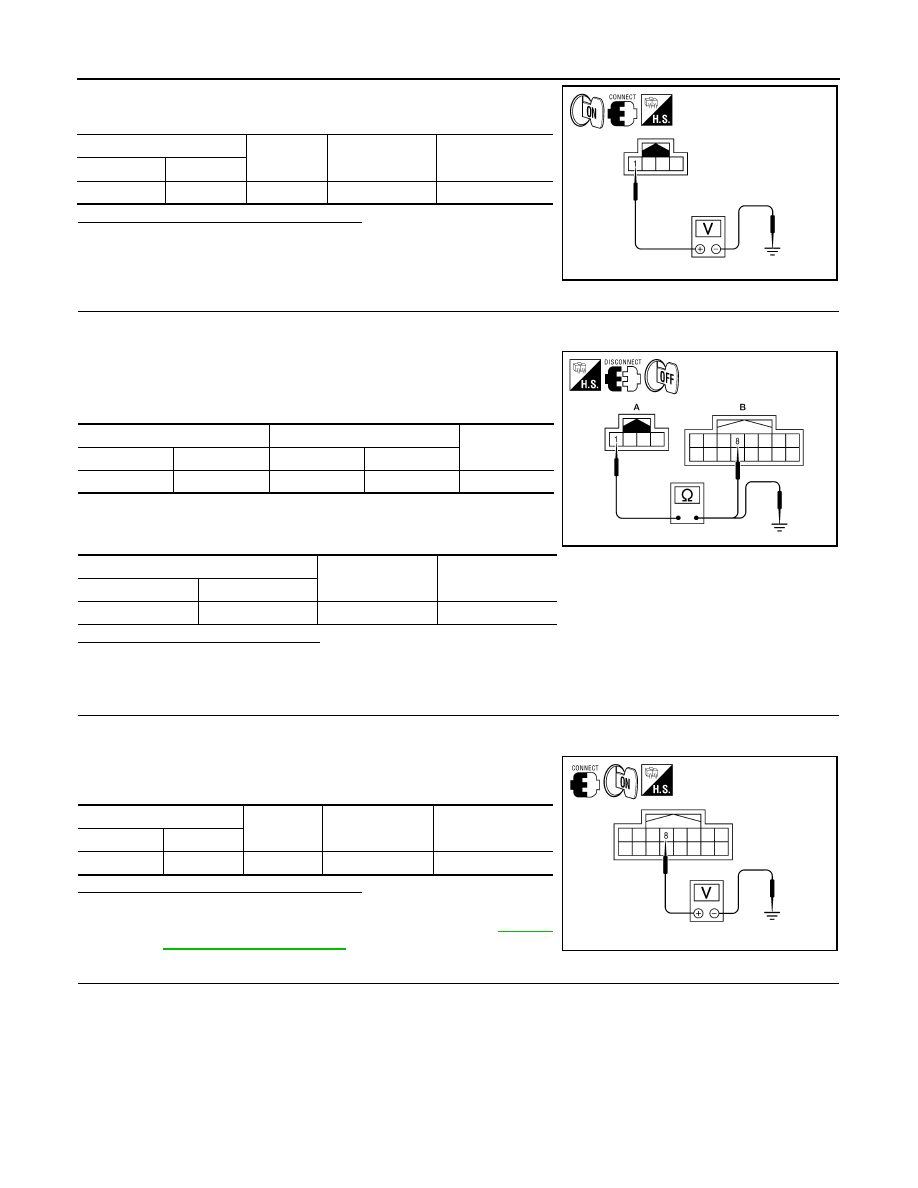
3.
CHECK POWER SUPPLY CIRCUIT (REAR VIEW CAMERA CONTROL UNIT SIDE)
1.
Connect rear view camera control unit harness connector.
2.
Turn ignition switch ON.
3.
Check voltage between rear view camera control unit harness
connector B176 and ground.
Is voltage reading approximately 6 volts?
YES
>> GO TO 4.
NO
>> Replace rear view camera control unit. Refer to
.
4.
CHECK GROUND CIRCUIT
1.
Turn ignition switch OFF.
2.
Disconnect rear view camera harness connector.
(+)
(-)
Transmission
position
Value (Approx.)
Connector
Terminal
D551
1
Ground
Reverse
6V
ALLIA0243ZZ
A
B
Continuity
Connector
Terminal
Connector
Terminal
D551
1
B176
8
Yes
A
—
Continuity
Connector
Terminal
D551
1
Ground
No
ALLIA0246ZZ
(+)
(-)
Transmission po-
sition
Value (Approx.)
Connector
Terminal
B176
8
Ground
Reverse
6V
ALLIA0247ZZ
2009 Pathfinder