Nissan Pathfinder (2008 year). Manual - part 581


  Index      Manuals     Nissan Pathfinder (2008 year) - Service and Repair Manual


Search            copyright infringement  


Content      ..     579      580      581      582     ..


Nissan Pathfinder (2008 year). Manual - part 581


B TERMINAL CIRCUIT

STR-9

< COMPONENT DIAGNOSIS >

C

D

E

F

G

H

I

J

K

L

M

A

STR

N

P

O

COMPONENT DIAGNOSIS

B TERMINAL CIRCUIT

Description

INFOID:0000000001714433

Terminal "2" (B) is constantly supplied with battery power.

Diagnosis Procedure

INFOID:0000000001714434

CAUTION:

Perform diagnosis under the condition that the engine cannot start by the following procedure.
1.

Remove fuel pump fuse.

2.

Crank or start the engine (where possible) until the fuel pressure is depleted.

1.

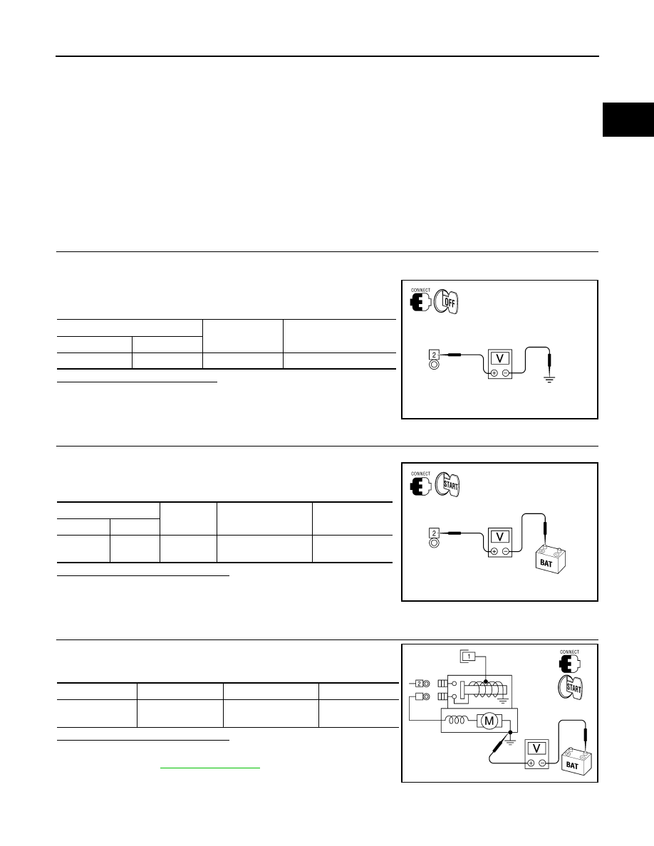
CHECK TERMINAL 2 POWER SUPPLY VOLTAGE

1.

Turn ignition switch OFF.

2.

Make sure that starter motor connector E210 terminal 2 connection is clean and tight.

3.

Check voltage between starter motor connector E210 terminal 2
and ground.

Is there battery voltage present?

YES

>> GO TO 2

NO

>> Check harness between battery and starter motor for

open circuit.

2.

CHECK BATTERY CABLE (VOLTAGE DROP TEST)

1.

Shift the transmission into park or neutral.

2.

Check voltage between battery positive terminal and starter
motor connector E210 terminal 2 while cranking the engine.

Is the voltage drop less than 0.2V?

YES

>> GO TO 3

NO

>> Check harness between the battery and the starter

motor for high resistance.

3.

CHECK GROUND CIRCUIT STATUS (VOLTAGE DROP TEST)

Check voltage between starter motor case and battery negative ter-
minal while cranking the engine.

Is the voltage drop less than 0.2V?

YES

>> Terminal 2 circuit is OK. Further inspection necessary.

Refer to 

STR-4, "Work Flow"

.

NO

>> Check the starter motor case to engine mounting for

high resistance.

(+)

(-)

Voltage

Connector

Terminal

E210

2

Ground

Battery voltage

AWBIA0122GB

(+)

(-)

Condition

Voltage

Connector

Terminal

E210

2

Battery (+) 

terminal

While cranking the 

engine

Less than 0.2V

ALBIA0471GB

(+)

(-)

Condition

Voltage

Starter motor 

case

Battery (-) terminal

While cranking the 

engine

Less than 0.2V

AWBIA0124GB

STR-10

< COMPONENT DIAGNOSIS >

S CONNECTOR CIRCUIT

S CONNECTOR CIRCUIT

Description

INFOID:0000000001714435

Terminal "1" (S) is the power supply for the starter motor magnetic switch. Terminal 1 is supplied with power
when the ignition switch is turned to the START position while the selector lever is in the P or N position.

Diagnosis Procedure

INFOID:0000000001714436

CAUTION:

Perform diagnosis under the condition that engine cannot start by the following procedure.
1.

Remove fuel pump fuse.

2.

Crank or start the engine (where possible) until the fuel pressure is released.

1.

CHECK STARTER MOTOR MAGNETIC SWITCH CIRCUIT

1.

Turn ignition switch OFF.

2.

Disconnect starter motor connector E207.

3.

Shift transmission into park or neutral.

4.

Check voltage between starter motor harness connector E207
terminal 1 and ground with the ignition in START.

Is battery voltage present?

YES

>> Magnetic switch circuit is OK. Further inspection necessary. Refer to 

STR-4, "Work Flow"

.

NO

>> GO TO 2

2.

CHECK CONNECTOR

1.

Turn ignition switch OFF.

2.

Check the IPDM E/R harness connector E120 and starter motor harness connector E207 for damage,
bent pins and loose connections.

Is the inspection result normal?

YES

>> GO TO 3

NO

>> Repair the terminal and connector.

3.

CHECK HARNESS CONTINUITY (OPEN CIRCUIT)

1.

Disconnect IPDM E/R connector E120 and starter motor con-
nector E207.

2.

Check continuity between starter motor harness connector E207
(A) terminal 1 and IPDM E/R harness connector E120 (B) termi-
nal 19.

3.

Check continuity between starter motor harness connector E207
(A) terminal 1 and ground.

Are the continuity test results as specified?

YES

>> Further inspection necessary. Refer to 

STR-4, "Work Flow"

.

NO

>> Repair the harness.

(+)

(-)

Condition

Voltage

Connector

Terminal

E207

1

Ground

While cranking the 

engine

Battery voltage

AWBIA0125GB

A

B

Continiuty

Connector

Terminal

Connector

Terminal

E207

1

E120

19

Yes

A

Continiuty

Connector

Terminal

E207

1

Ground

No

AWBIA0126GB

STARTING SYSTEM

STR-11

< COMPONENT DIAGNOSIS >

C

D

E

F

G

H

I

J

K

L

M

A

STR

N

P

O

STARTING SYSTEM

Wiring Diagram

INFOID:0000000001714437

ALBWA0165GB

STR-12

< COMPONENT DIAGNOSIS >

STARTING SYSTEM

ALBIA0419GB

STARTING SYSTEM

STR-13

< COMPONENT DIAGNOSIS >

C

D

E

F

G

H

I

J

K

L

M

A

STR

N

P

O

ALBIA0420GB

STR-14

< COMPONENT DIAGNOSIS >

STARTING SYSTEM

ALBIA0421GB

STARTING SYSTEM

STR-15

< COMPONENT DIAGNOSIS >

C

D

E

F

G

H

I

J

K

L

M

A

STR

N

P

O

ALBIA0422GB

STR-16

< SYMPTOM DIAGNOSIS >

STARTING SYSTEM

SYMPTOM DIAGNOSIS

STARTING SYSTEM

Symptom Table

INFOID:0000000001714438

Symptom

Reference

No normal cranking

Refer to 

STR-4, "Work Flow"

.

Starter motor does not rotate


Content      ..     579      580      581      582     ..