Nissan Pathfinder (2008 year). Manual - part 495


  Index      Manuals     Nissan Pathfinder (2008 year) - Service and Repair Manual


Search            copyright infringement  


Content      ..     493      494      495      496     ..


Nissan Pathfinder (2008 year). Manual - part 495


MWI

POWER SUPPLY AND GROUND CIRCUIT

MWI-31

< COMPONENT DIAGNOSIS >

C

D

E

F

G

H

I

J

K

L

M

B

A

O

P

Is the fuse blown?

YES

>> Replace the blown fuse or fusible link after repairing the affected circuit.

NO

>> GO TO 2

2.

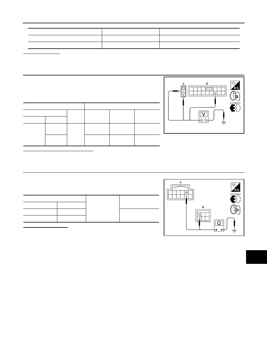
 CHECK BATTERY POWER SUPPLY CIRCUIT

1.

Turn ignition switch OFF.

2.

Disconnect IPDM E/R.

3.

Check voltage between IPDM E/R harness connectors and
ground.

Is the measurement value normal?

YES

>> GO TO 3

NO

>> Repair or replace harness.

3.

 CHECK GROUND CIRCUIT

1.

Turn ignition switch OFF.

2.

Check continuity between IPDM E/R harness connectors and
ground.

Does continuity exist?

YES

>> Inspection End.

NO

>> Repair or replace harness.

Terminal No.

Signal name

Fuses and fusible link No.

1

Battery

A, D

2

Battery

C

Terminals

Ignition switch position

(+)

(

)

OFF

ON

START

Connector

Terminal

E118 (A)

1

Ground

Battery
voltage

Battery
voltage

Battery
voltage

2

Battery
voltage

Battery
voltage

Battery
voltage

AWMIA0023ZZ

IPDM E/R

Ground

Continuity

Connector

Terminal

E122 (A)

38

Yes

E124 (B)

59

AWMIA0024ZZ

MWI-32

< COMPONENT DIAGNOSIS >

FUEL LEVEL SENSOR SIGNAL CIRCUIT

FUEL LEVEL SENSOR SIGNAL CIRCUIT

Description

INFOID:0000000001702272

The fuel level sensor unit and fuel pump detects the approximate fuel level in the fuel tank and transmits the
fuel level signal to the combination meter.

Component Function Check

INFOID:0000000001702273

1.

COMBINATION METER INPUT SIGNAL

1.

Select “METER/M&A” on CONSULT-III.

2.

Using “FUEL METER” of “DATA MONITOR”, compare the value of DATA MONITOR with fuel gauge
pointer of combination meter.

Does the data monitor value approximately match the fuel gauge indication?

YES

>> Inspection End.

NO

>> Replace combination meter. Refer to 

MWI-94, "Removal and Installation"

.

Diagnosis Procedure

INFOID:0000000001702274

1.

CHECK HARNESS CONNECTOR

1.

Turn ignition switch OFF.

2.

Check combination meter and fuel level sensor unit terminals (meter-side and harness-side) for poor con-
nection.

Is the inspection result normal?

YES

>> GO TO 2

NO

>> Repair or replace terminals or connectors.

2.

CHECK FUEL LEVEL SENSOR UNIT CIRCUIT

1.

Disconnect combination meter connector and fuel level sensor
unit connector.

2.

Check continuity between combination meter harness connector
and fuel level sensor unit and fuel pump harness connector.

3.

Check continuity between fuel level sensor unit and fuel pump
harness connector and ground.

Is the inspection result normal?

YES

>> GO TO 3

Fuel gauge pointer

Reference value of data monitor [lit.]

Full

Approx. 79.3

3/4

Approx. 58.5

1/2

Approx. 37.1

1/4

Approx. 22.4

Empty

Approx. 7.6

Terminals

Continuity

(+)

(-)

Connector

Terminal

Connector

Terminal

C5

2

M24

9

Yes

Terminals

Continuity

(+)

(-)

Connector

Terminal

Ground

C5

2

No

WKIA3288E

MWI

FUEL LEVEL SENSOR SIGNAL CIRCUIT

MWI-33

< COMPONENT DIAGNOSIS >

C

D

E

F

G

H

I

J

K

L

M

B

A

O

P

NO

>> Repair harness or connector.

3.

CHECK FUEL LEVEL SENSOR UNIT GROUND CIRCUIT

1.

Check continuity between combination meter harness connector
and fuel level sensor unit and fuel pump harness connector.

2.

Check continuity between fuel level sensor unit and fuel pump
harness connector and ground.

Is the inspection result normal?

YES

>> GO TO 4

NO

>> Repair harness or connector.

4.

CHECK INSTALLATION CONDITION

Check fuel level sensor unit installation, and check whether the float arm interferes or binds with any of the
internal components in the fuel tank.

Is the inspection result normal?

YES

>> Inspection End.

NO

>> Install the fuel level sensor unit properly.

Component Inspection

INFOID:0000000001702275

1.

REMOVE FUEL LEVEL SENSOR UNIT

Remove the fuel level sensor unit. Refer to 

FL-11, "Removal and Installation"

>> GO TO 2

2.

CHECK FUEL LEVEL SENSOR UNIT AND FUEL PUMP

Check the resistance between terminals 2 and 5.

*1 and *2: When float arm is in contact with stopper.

Is inspection result normal?

YES

>> Inspection End.

NO

>> Replace fuel level sensor unit and fuel pump. Refer to

FL-11, "Removal and Installation"

.

Terminals

Continuity

(+)

(-)

Connector

Terminal

Connector

Terminal

C5

5

M24

4

Yes

Terminals

Continuity

(+)

(-)

Connector

Terminal

Ground

C5

5

No

WKIA3289E

Terminal

Float position

mm (in)

Resistance value

(Approx.)

2

5

*1

Empty

10 (0.4)

81.5

*2

Full

211.1 (8.3)

5

LKIA0402E

MWI-34

< COMPONENT DIAGNOSIS >

OIL PRESSURE SWITCH SIGNAL CIRCUIT

OIL PRESSURE SWITCH  SIGNAL CIRCUIT

Description

INFOID:0000000001702276

Detects the engine oil pressure and transmits the oil pressure switch signal to the IPDM E/R.

Component Function Check

INFOID:0000000001702277

1.

COMBINATION METER INPUT SIGNAL

1.

Select “METER/M&A” on CONSULT-III.

2.

Monitor “OIL W/L” of “DATA MONITOR” while operating ignition switch.

>> Inspection End.

Diagnosis Procedure

INFOID:0000000001702278

1.

CHECK OIL PRESSURE SWITCH CIRCUIT

1.

Turn ignition switch OFF.

2.

Disconnect IPDM E/R connector E122 and oil pressure switch
connector E208 (VQ40DE) or F4 (VK56DE).

3.

Check continuity between IPDM E/R harness connector E122
(A) terminal 42 and oil pressure switch harness connector E208
(VQ40DE) or F4 (VK56DE) (B) terminal 1.

Is the inspection result normal?

YES

>> Inspection End.

NO

>> Repair harness or connector.

Component Inspection

INFOID:0000000001702279

1.

CHECK OIL PRESSURE SWITCH

Check continuity between oil pressure switch and ground.

Is the inspection result normal?

YES

>> Inspection End.

NO

>> Replace the oil pressure switch.

OIL W/L

When ignition switch is in ON 
position (Engine stopped)

: ON

When engine is running

: OFF

Continuity should exist.

WKIA5607E

Condition

Oil pressure [kPa (kg/cm

2

, psi)]

Continuity

Engine stopped

Less than 29 (0.3, 4)

Yes

Engine running

More than 29 (0.3, 4) 

No

ELF0044D

MWI

COMPASS

MWI-35

< COMPONENT DIAGNOSIS >

C

D

E

F

G

H

I

J

K

L

M

B

A

O

P

COMPASS

Wiring Diagram - With HomeLink® Universal Transceiver -

INFOID:0000000001723019

ALNWA0101GB

MWI-36

< COMPONENT DIAGNOSIS >

COMPASS

ALNIA0626GB

MWI

COMPASS

MWI-37

< COMPONENT DIAGNOSIS >

C

D

E

F

G

H

I

J

K

L

M

B

A

O

P

ALNIA0627GB

MWI-38

< COMPONENT DIAGNOSIS >

COMPASS

Wiring Diagram - Without HomeLink® Universal Transceiver -

INFOID:0000000001702287

ALNWA0102GB


Content      ..     493      494      495      496     ..