Nissan Pathfinder (2008 year). Manual - part 233


  Index      Manuals     Nissan Pathfinder (2008 year) - Service and Repair Manual


Search            copyright infringement  


Content      ..     231      232      233      234     ..


Nissan Pathfinder (2008 year). Manual - part 233


DLN-448

< REMOVAL AND INSTALLATION >

[REAR FINAL DRIVE: R230 (4WD)]

REAR FINAL DRIVE

7.

Place a suitable jack under the rear final drive assembly.

CAUTION:

Do not place the jack on the carrier cover.

8.

Remove the nuts and bolts and remove the rear final drive
assembly.

CAUTION:

Secure rear final drive assembly to the jack while removing
it.

INSTALLATION

Installation is in the reverse order of removal.

CAUTION:

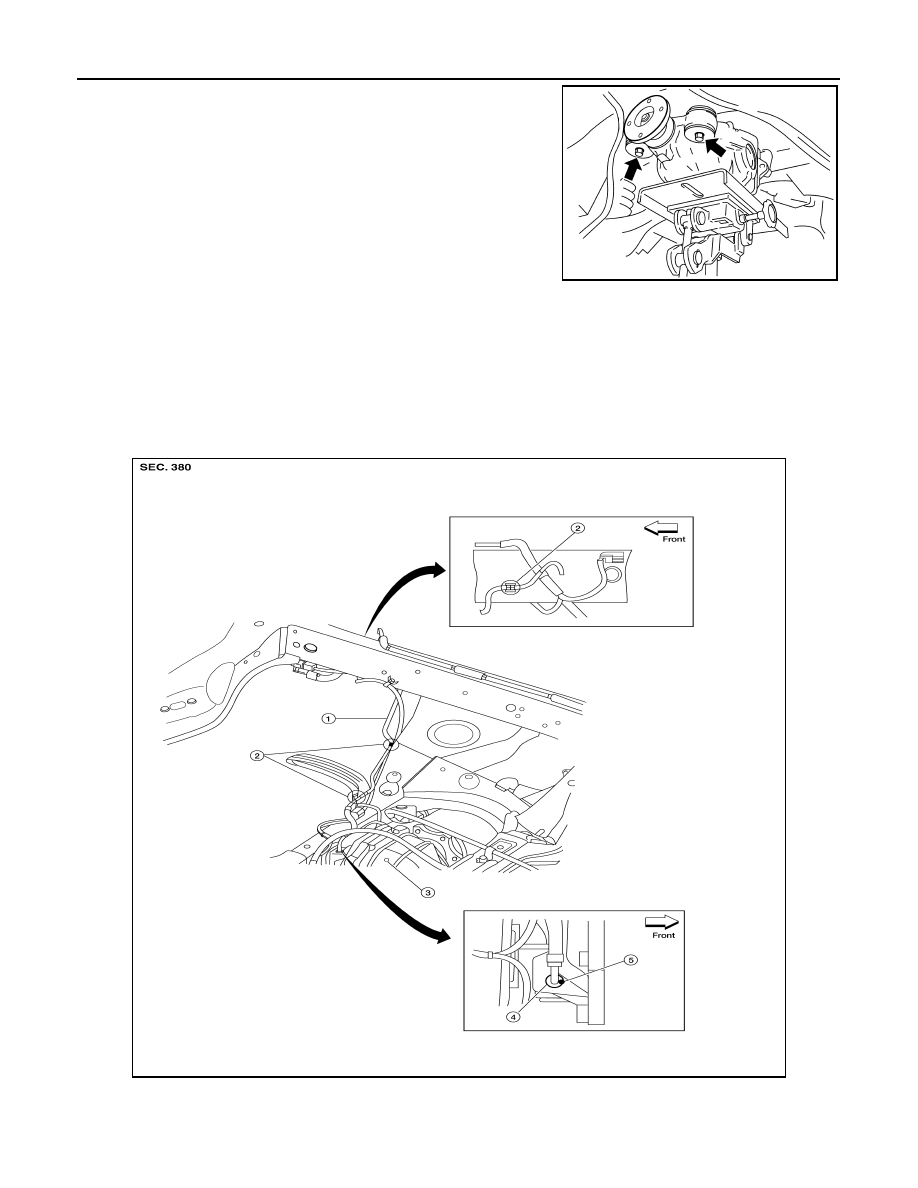
• When installing the breather hose make sure the painted marking on the metal end of breather hose

is to the front of the vehicle and there are no pinched or restricted areas on the breather hose
caused by folding or bending when installing it.

• When installing the breather hose insert the plastic end of the breather hose into the hole in the sus-

pension member.

REAR FINAL DRIVE BREATHER

WDIA0117E

LDIA0166E

1.

Breather hose

2.

Plastic connector

3.

Rear final drive assembly

4.

Metal connector

5.

Paint mark

REAR FINAL DRIVE

DLN-449

< REMOVAL AND INSTALLATION >

[REAR FINAL DRIVE: R230 (4WD)]

C

E

F

G

H

I

J

K

L

M

A

B

DLN

N

O

P

• Fill the rear final drive assembly with differential gear oil after installation. Refer to 

DLN-441, "Chang-

ing Differential Gear Oil"

.

DLN-450

< DISASSEMBLY AND ASSEMBLY >

[REAR FINAL DRIVE: R230 (4WD)]

REAR FINAL DRIVE

DISASSEMBLY AND ASSEMBLY

REAR FINAL DRIVE

Disassembly and Assembly

INFOID:0000000001316530

COMPONENTS

WDIA0191E

REAR FINAL DRIVE

DLN-451

< DISASSEMBLY AND ASSEMBLY >

[REAR FINAL DRIVE: R230 (4WD)]

C

E

F

G

H

I

J

K

L

M

A

B

DLN

N

O

P

ASSEMBLY INSPECTION AND ADJUSTMENT

• Drain the differential gear oil before inspection and adjustment. Refer to 

DLN-441

.

• Remove and install the carrier cover as necessary for inspection and adjustment. Refer to 

DLN-446

.

Total Preload Torque

1.

Remove the side flanges if necessary. Refer to 

DLN-444, "Removal and Installation"

.

CAUTION:

The side flanges shaft must removed in order to measure total preload torque. 

2.

Rotate the drive pinion back and forth 2 to 3 times to check for unusual noise and rotation malfunction.

3.

Rotate the drive pinion at least 20 times to check for smooth operation of the bearings.

4.

Measure the total preload torque using Tool.

NOTE:
Total preload torque = Drive pinion bearing preload torque +
Side bearing preload torque

• If the measured value is out of the specification, check and adjust each part. Adjust the drive pinion

bearing preload torque first, then adjust the side bearing preload torque.

CAUTION:

Select a side bearing adjusting washer for right and left individually.

Drive Gear Runout

1.

Drive pinion lock nut

2.

Companion flange

3.

Front oil seal

4.

Drive pinion front bearing 

5.

Collapsible spacer

6.

Drive pinion rear bearing

7.

Drive pinion height adjusting 
washer

8.

Drive pinion

9.

Gear carrier

10. Drive gear

11.

Pinion mate shaft

12. Lock pin

13. Pinion mate gear

14. Pinion mate thrust washer

15. Side gear

16. Side gear thrust washer

17. Differential case

18. Side bearing

19. Side bearing adjusting washer

20. Bearing cap

21. Carrier cover

22. Filler plug

23. Drain plug

24. Side oil seal

Tool number

: ST3127S000 (J-25765-A)

Total preload torque:

2.05 - 4.11 N·m (0.21 - 0.42 kg-m, 19 - 36 in-lb)

SPD884

If the total preload torque is greater than specification

On drive pinion bearings:

Replace the collapsible spacer.

On side bearings:

Use thinner side bearing adjusting washers by the same 
amount on each side. Refer to 

DLN-466, "Inspection and Adjust-

ment"

.

If the total preload torque is less than specification

On drive pinion bearings:

Tighten the drive pinion lock nut.

On side bearings:

Use thicker side bearing adjusting washers by the same 
amount on each side. Refer to 

DLN-466, "Inspection and Ad-

justment"

.

DLN-452

< DISASSEMBLY AND ASSEMBLY >

[REAR FINAL DRIVE: R230 (4WD)]

REAR FINAL DRIVE

1.

Fit a dial indicator to the drive gear back face.

2.

Rotate the drive gear to measure runout.

• If the runout is outside of the limit, check the condition of the drive

gear assembly. Foreign material may be caught between the drive
gear and differential case, or the differential case or drive gear may
be deformed.

CAUTION:

Replace drive gear and drive pinion as a set.

Tooth Contact

1.

Apply red lead to the drive gear.
NOTE:
Apply red lead to both faces of three to four gears, at four loca-
tions evenly spaced on the drive gear.

2.

Rotate the drive gear back and forth several times. Then check
for correct drive pinion to drive gear tooth contact as shown.

CAUTION:

Check tooth contact on drive side and reverse side.

3.

If the tooth contact is improperly adjusted, follow the procedure
below to adjust the pinion height (dimension X).

Runout limit

: 0.05 mm (0.0020 in) or less

SPD886

SPD357

SDIA0570E

SDIA0517E

REAR FINAL DRIVE

DLN-453

< DISASSEMBLY AND ASSEMBLY >

[REAR FINAL DRIVE: R230 (4WD)]

C

E

F

G

H

I

J

K

L

M

A

B

DLN

N

O

P

• If the tooth contact is near the face (face contact), or near the heel

(heel contact), use a thicker drive pinion height adjusting washers
to move the drive pinion closer to the drive gear.
Refer to 

DLN-466, "Inspection and Adjustment"

.

• If the tooth contact is near the flank (flank contact), or near the toe

(toe contact), use a thinner drive pinion height adjusting washers to
move the drive pinion farther from the drive gear.
Refer to 

DLN-466, "Inspection and Adjustment"

.

Backlash

1.

Fit a dial indicator to the drive gear face to measure the back-
lash.

• If the backlash is outside of the specification, change the thickness

of the side bearing adjusting washers.

CAUTION:

Do not change the total thickness of side bearing adjusting washers as it will change the side bearing
preload torque.

Companion Flange Runout

PDIA0440E

PDIA0441E

Backlash

: 0.13 - 0.18 mm (0.0051 - 0.0070 in)

If the backlash is greater than specification:

Make side bearing adjusting washer thicker on drive 
gear back side, and side bearing adjusting washer 
thinner on drive gear tooth side by the same amount. 
Refer to 

DLN-466, "Inspection and Adjustment"

.

If the backlash is less than specification:

Make side bearing adjusting washer thinner on drive 
gear back side, and side bearing adjusting washer 
thicker on drive gear tooth side by the same amount. 
Refer to 

DLN-466, "Inspection and Adjustment"

.

SPD513

DLN-454

< DISASSEMBLY AND ASSEMBLY >

[REAR FINAL DRIVE: R230 (4WD)]

REAR FINAL DRIVE

1.

Rotate companion flange and check for runout on the outer face
of the companion flange using suitable tool.

2.

If the runout is outside of the runout limit, follow the procedure
below to adjust.

a.

Rotate the companion flange on the drive pinion by 90

°

, 180

°

and 270

°

 while checking for the position where the runout is

minimum.

b.

If the runout is still outside of the runout limit after the companion
flange has been rotated on the drive pinion, possible cause
could be an assembly malfunction of drive pinion and drive pinion bearing or a malfunctioning drive pinion
bearing.

c.

If the runout is still outside of the runout limit after repair of the assembly of drive pinion and drive pinion
bearing or drive pinion bearing, replace the companion flange.

DISASSEMBLY

Side Flange

1.

Drain the differential gear oil if necessary.

2.

Remove the side flange using Tools.

3.

Remove the side oil seal using suitable tool.

CAUTION:

Do not to damage gear carrier.

Differential Assembly

1.

Remove the side flanges. Refer to 

DLN-444, "Removal and Installation"

.

2.

Remove the carrier cover bolts.

3.

Remove the carrier cover bolts and separate the carrier cover
from the gear carrier using Tool.

CAUTION:

• Do not damage the mating surface.
• Do not insert flat-bladed screwdriver, this will damage the

mating surface.

4.

Mount the carrier on the Tool using two 45 mm (1.77 in) spacers.

Runout limit

: 0.08 mm (0.0031 in) or less

WDIA0231E

Tool numbers

A: KV40104100 (

)

B: ST36230000 (J-25840-A)

Tool number

: KV10111100 (J-37228)

WDIA0123E

Tool number

: KV38100800 (J-25604-01)

SPD888

REAR FINAL DRIVE

DLN-455

< DISASSEMBLY AND ASSEMBLY >

[REAR FINAL DRIVE: R230 (4WD)]

C

E

F

G

H

I

J

K

L

M

A

B

DLN

N

O

P

5.

For proper reinstallation, paint matching marks on one side of
the side bearing cap and gear carrier.

CAUTION:

• For matching marks, use paint. Do not damage side bear-

ing cap or gear carrier.

• Side bearing caps are line-board during manufacture. The

matching marks are used to reinstall them in their original
positions.

6.

Remove the side bearing caps.

7.

Lift the differential case assembly out using Tool.

CAUTION:

• Keep side bearing outer races together with inner race.

Do not mix them up.

• Keep side bearing adjusting washers together with side

bearings.

SDIA1795E

S-PD343

Tool number

: HT72400000 (

)

S-PD344

SPD919


Content      ..     231      232      233      234     ..