Nissan Pathfinder (2008 year). Manual - part 230


  Index      Manuals     Nissan Pathfinder (2008 year) - Service and Repair Manual


Search            copyright infringement  


Content      ..     228      229      230      231     ..


Nissan Pathfinder (2008 year). Manual - part 230


DLN-424

< DISASSEMBLY AND ASSEMBLY >

[REAR FINAL DRIVE: R200]

REAR FINAL DRIVE

• Drive pinion front bearing; make sure the J-34309-3 drive

pinion front bearing seat is secured tightly against the J-
34309-2 gauge anvil. Then turn the J-34309-5 drive pinion
front bearing pilot to secure the drive pinion bearing in its
proper position.

• Drive pinion rear bearing; the J-34309-8 drive pinion rear

bearing pilot is used to center the drive pinion rear bearing
only. The J-34309-4 drive pinion rear bearing locking seat is
used to lock the drive pinion rear bearing to the assembly.

• Installation of J-34309-9 and J-34309-16; place a suitable

2.5 mm (0.098 in) thick plain washer between J-34309-9 and
J-34309-16. Both surfaces of J-34309-9 and J-34309-16 must
be parallel with a clearance of 2.5 mm (0.098 in).
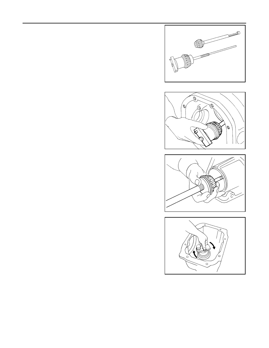
3.

Install the drive pinion rear bearing inner race into the gear car-
rier. Then insert the drive pinion height adjusting washer selec-
tor tool, J-34309-1, gauge screw assembly.

4.

Assemble the drive pinion front bearing inner race and the J-
34309-2 gauge anvil. Assemble them together with the J-34309-
1 gauge screw in the gear carrier. Make sure that the drive pin-
ion height gauge plate, J-34309-16, will turn a full 360

°

. Tighten

the two sections together by hand.

5.

Turn the assembly several times to seat the drive pinion bear-
ings.

SPD197A

SPD893

SPD199A

SPD770

REAR FINAL DRIVE

DLN-425

< DISASSEMBLY AND ASSEMBLY >

[REAR FINAL DRIVE: R200]

C

E

F

G

H

I

J

K

L

M

A

B

DLN

N

O

P

6.

Measure the turning torque at the end of the J-34309-2 gauge
anvil using Tool.

7.

Place the J-34309-11 “R200A” drive pinion height adapter onto
the gauge plate and tighten it by hand.

CAUTION:

Make sure all machined surfaces are clean.

8.

Position the side bearing discs, Tool, and arbor firmly into the
side bearing bores. Install the side bearing caps and tighten the
side bearing cap bolts to the specified torque. Refer to 

DLN-413,

"Disassembly and Assembly"

.

9.

Select the correct standard drive pinion height adjusting washer
thickness. Select by using a standard gauge of 3 mm (0.12 in)
and your J-34309-101 feeler gauge. Measure the distance
between the J-34309-11 drive pinion height adapter, including
the standard gauge and the arbor.

10. Write down the exact measurement (the value of feeler gauge).

Tool number

: ST3127S000 (J-25765- A)

Turning torque:

1.0 - 1.3 N·m (0.11 - 0.13 kg-m, 
9 - 11 in-lb)

PDIA0566E

SPD208A

Tool number

 (J-25269-4)

SPD211A

SPD204A

SPD775

DLN-426

< DISASSEMBLY AND ASSEMBLY >

[REAR FINAL DRIVE: R200]

REAR FINAL DRIVE

11. Correct the drive pinion height adjusting washer size by referring

to the drive pinion “head number”.
There are two numbers painted on the drive pinion. The first
one refers to the drive pinion and drive gear as a matched
set. This number should be the same as the number on the
drive gear. The second number is the drive pinion “head
number”. It refers to the ideal drive pinion height from stan-
dard for quietest operation. Use the following chart to
determine the correct drive pinion height adjusting washer.

12. Select the correct drive pinion height adjusting washer. Refer to 

DLN-432, "Inspection and Adjustment"

.

13. Remove the Tool from the gear carrier and disassemble to

retrieve the drive pinion bearings.

ASSEMBLY

Drive Pinion Assembly

Head number

Add or remove from the standard drive pinion 

height adjusting washer thickness measurement

- 6
- 5
- 4
- 3
- 2
- 1

0

+1
+2
+3
+4
+5 
+6

Add 0.06 mm (0.0024 in)
Add 0.05 mm (0.0020 in)
Add 0.04 mm (0.0016 in)
Add 0.03 mm (0.0012 in)
Add 0.02 mm (0.0008 in)
Add 0.01 mm (0.0004 in)

Use the selected washer thickness

Subtract 0.01 mm (0.0004 in)
Subtract 0.02 mm (0.0008 in)
Subtract 0.03 mm (0.0012 in)
Subtract 0.04 mm (0.0016 in)
Subtract 0.05 mm (0.0020 in)
Subtract 0.06 mm (0.0024 in)

Tool number

 (J-34309)

SPD542

SPD205A

REAR FINAL DRIVE

DLN-427

< DISASSEMBLY AND ASSEMBLY >

[REAR FINAL DRIVE: R200]

C

E

F

G

H

I

J

K

L

M

A

B

DLN

N

O

P

1.

Install the drive pinion front and rear bearing outer races using
Tools.

CAUTION:

• First tap the drive pinion bearing outer race until it

becomes flush with the gear carrier.

• Do not reuse drive pinion front and rear bearing outer

race.

2.

Select a drive pinion height adjusting washer. Refer to 

DLN-413, "Disassembly and Assembly"

.

3.

Install the selected drive pinion height adjusting washer to the
drive pinion. Press the drive pinion rear bearing inner race to it
using Tool.

CAUTION:

• Install the drive pinion height adjusting washer in the

proper direction as shown.

• Do not reuse drive pinion rear bearing inner race.

4.

Assemble the collapsible spacer to the drive pinion.

CAUTION:

Do not reuse collapsible spacer.

5.

Apply differential gear oil to the drive pinion rear bearing, and
install the drive pinion assembly to the gear carrier.

6.

Apply differential gear oil to the drive pinion front bearing, and
install the drive pinion front bearing inner race to the drive pinion
assembly.

CAUTION:

Do not reuse drive pinion front bearing inner race.

Tool number

A: ST30720000 (J-25405)

B: KV40105230 (

)

C: ST30611000 (J-25742-1)

D: ST30613000 (J-25742-3)

PDIA0562E

Tool number

: ST30901000 (J-26010-01)

SDIA0048E

PDIA0492E

DLN-428

< DISASSEMBLY AND ASSEMBLY >

[REAR FINAL DRIVE: R200]

REAR FINAL DRIVE

7.

Press the drive pinion front bearing inner race to the drive pinion
as far as drive pinion lock nut can be tightened using suitable
spacer.

8.

Apply multi-purpose grease to the lips and differential gear oil to
the circumference of the new front oil seal. Then drive the new
front oil seal in evenly until it becomes flush with the gear carrier
using Tool.

CAUTION:

• Do not reuse front oil seal.
• Do not incline the new front oil seal when installing.
• Apply multi-purpose grease to the lips and differential

gear oil to the circumference of the new front oil seal.

9.

Install the companion flange to the drive pinion while aligning the matching marks.

10. Apply anti-corrosive oil to the threads of the drive pinion and the

seating surface of the new drive pinion lock nut. Then adjust the
drive pinion lock nut tightening torque using Tool A, and check
the drive pinion bearing preload torque using Tool B.

CAUTION:

• Do not reuse drive pinion lock nut.
• Apply anti-corrosive oil to the threads of the drive pinion

and the seating surface of the new drive pinion lock nut.

• Adjust the drive pinion lock nut tightening torque to the

lower limit first. Do not exceed the drive pinion lock nut
specified torque. Refer to 

DLN-413, "Disassembly and

Assembly"

.

• If the drive pinion bearing preload torque exceeds the

specified value, replace collapsible spacer and tighten it
again to adjust. Do not loosen drive pinion lock nut to
adjust the drive pinion bearing preload torque.

• After adjustment, rotate drive pinion back and forth 2 to 3

times to check for unusual noise, rotation malfunction, and other malfunctions.

11. Check companion flange runout. Refer to 

DLN-413, "Disassembly and Assembly"

.

12. Install the differential case assembly. Refer to 

DLN-410, "Removal and Installation"

.

Differential Assembly

SPD896

Tool number

: ST30720000 (J-25405)

PDIA0563E

Tool number

A: KV40104000 (

)

B: ST3127S000 (J-25765-A)

Drive pinion bearing preload torque:

2.65 - 3.23 N·m (0.27 - 0.32 kg-m, 24 - 28 in-lb)

WDIA0379E

REAR FINAL DRIVE

DLN-429

< DISASSEMBLY AND ASSEMBLY >

[REAR FINAL DRIVE: R200]

C

E

F

G

H

I

J

K

L

M

A

B

DLN

N

O

P

1.

Install side gear thrust washers with the same thickness as the
ones installed prior to disassembly, or reinstall the old ones on
the side gears.

2.

Install the side gears and side gear thrust washers into the dif-
ferential case.

CAUTION:

Make sure that the circular clip is installed to side gears.

3.

Install the pinion mate thrust washers to the two pinion mate
gears. Then install the pinion mate gears with the pinion mate
thrust washers by aligning them in diagonally opposite positions
and rotating them into the differential case.

4.

Align the lock pin hole on the differential case with the lock pin
hole on the pinion mate shaft, and install the pinion mate shaft.

5.

Measure the side gear end play. If necessary, select the appro-
priate side gear thrust washers. Refer to 

DLN-432, "Inspection

and Adjustment"

.

6.

Drive a new lock pin into the pinion mate shaft until it is flush
with the differential case using suitable tool.

CAUTION:

Do not reuse lock pin.

7.

Align the matching mark of the differential case with the mark of
the drive gear, then place the drive gear onto the differential
case.

SDIA0193J

SDIA2025E

SDIA0195J

WDIA0131E

SDIA2593E

DLN-430

< DISASSEMBLY AND ASSEMBLY >

[REAR FINAL DRIVE: R200]

REAR FINAL DRIVE

8.

Apply thread locking sealant into the threaded holes of the drive
gear and install the bolts.
• Use Genuine Medium Strength Thread Locking Sealant or

equivalent. Refer to 

GI-26, "Recommended Chemical Prod-

ucts and Sealants"

.

CAUTION:

Make sure the drive gear back and threaded holes are
clean.

9.

Tighten the drive gear bolts to the specified torque. Refer to

DLN-413, "Disassembly and Assembly"

. After tightening the

drive gear bolts to the specified torque, tighten an additional 31

°

to 36

°

 using Tool.

CAUTION:

• Always use Tool. Avoid tightening based on visual check

alone.

• Tighten drive gear bolts in a crisscross pattern.

10. Press the side bearing inner races into the differential case

using Tools.

CAUTION:

Do not reuse side bearing inner race.

11. Install the differential case assembly with the side bearing outer

races into the gear carrier.

12. Measure the side bearing preload torque. If necessary, select

the appropriate side bearing adjusting washers. Refer to 

DLN-

413, "Disassembly and Assembly"

.

13. Insert the selected left and right side bearing adjusting washers

in place between the side bearings and gear carrier.

SDIA2594E

Tool number

: KV10112100-A (BT-8653-A)

SDIA0247J

Tool number

A: KV38100300 (J-25523)

B: ST33061000 (J-8107-2)

SPD353

SPD919

SPD924

REAR FINAL DRIVE

DLN-431

< DISASSEMBLY AND ASSEMBLY >

[REAR FINAL DRIVE: R200]

C

E

F

G

H

I

J

K

L

M

A

B

DLN

N

O

P

14. Install the side bearing caps with the matching marks aligned

and tighten the side bearing cap bolts to the specified torque.
Refer to 

DLN-413, "Disassembly and Assembly"

.

15. Check and adjust the drive gear runout, tooth contact, drive gear to drive pinion backlash, and total pre-

load torque. Refer to 

DLN-432, "Inspection and Adjustment"

Recheck the above items.

16. Install the side flanges. Refer to 

DLN-413, "Disassembly and Assembly"

.

17. Apply a 3.2mm (0.126 in) bead of sealant to the mating surface

of the carrier cover.
• Use Genuine Silicone RTV or equivalent. Refer to 

GI-26,

"Recommended Chemical Products and Sealants"

.

CAUTION:

Remove any old sealant adhering to the mating surfaces.
Also remove any moisture, oil, or foreign material adhering
to the application and mating surfaces.

18. Install the carrier cover to the gear carrier. Tighten the bolts to

the specified torque. Refer to 

DLN-413, "Disassembly and

Assembly"

.

19. Install the side flange. Refer to 

DLN-413, "Disassembly and

Assembly"

.

Side Flange

1.

Apply multi-purpose grease to the lips and differential gear oil to
the circumference of the new side oil seal. Then drive the new
side oil seal in evenly until it becomes flush with the gear carrier
using Tool.

CAUTION:

• Do not reuse side oil seal.
• Do not incline the new side oil seal when installing.
• Apply multi-purpose grease to the lips and differential

gear oil to the circumference of the new side oil seal.

2.

Install the side flange using Tool.

a.

Install the Tool to the side oil seal as shown.

b.

Insert the side flange until the serrated part of the side flange
has engaged the serrated part of the side gear and remove the
Tool.

c.

Drive in the side flange using suitable tool.
NOTE:
Installation is completed when the driving sound of the side
flange turns into a sound which seems to affect the whole rear
final drive assembly.

SPD889

WDIA0282E

Tool number

: KV38100200 (J-26233)

SPD560

Tool number

: KV38107900 (J-39352)

SDIA0822E


Content      ..     228      229      230      231     ..