Nissan Pathfinder (2008 year). Manual - part 196
DLN-152
< DISASSEMBLY AND ASSEMBLY >
[TRANSFER: ATX14B]
TRANSFER ASSEMBLY
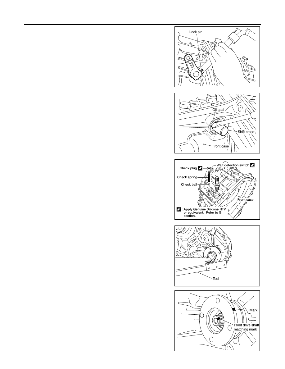
3.
Remove the lock pin using suitable tool.
4.
Remove the shift lever.
5.
Remove the side oil seal from the front case using suitable tool.
CAUTION:
Do not damage front case or shift cross.
6.
Remove the check plug, check spring and check ball.
7.
Remove the wait detection switch.
8.
Remove the self-lock nut from the companion flange using Tool.
9.
Put a matching mark on top of the front drive shaft thread in line
with the mark on the companion flange.
CAUTION:
Use paint to make the matching mark on the front drive
shaft thread. Never damage the front drive shaft.
SDIA2150E
SDIA2166E
WDIA0196E
Tool number
: KV40104000 (
—
)
SDIA2841E
SDIA2779E