Nissan Pathfinder (2008 year). Manual - part 63


  Index      Manuals     Nissan Pathfinder (2008 year) - Service and Repair Manual


Search            copyright infringement  


Content      ..     61      62      63      64     ..


Nissan Pathfinder (2008 year). Manual - part 63


AV-344

< COMPONENT DIAGNOSIS >

[BOSE AUDIO WITH NAVIGATION]

POWER SUPPLY AND GROUND CIRCUIT

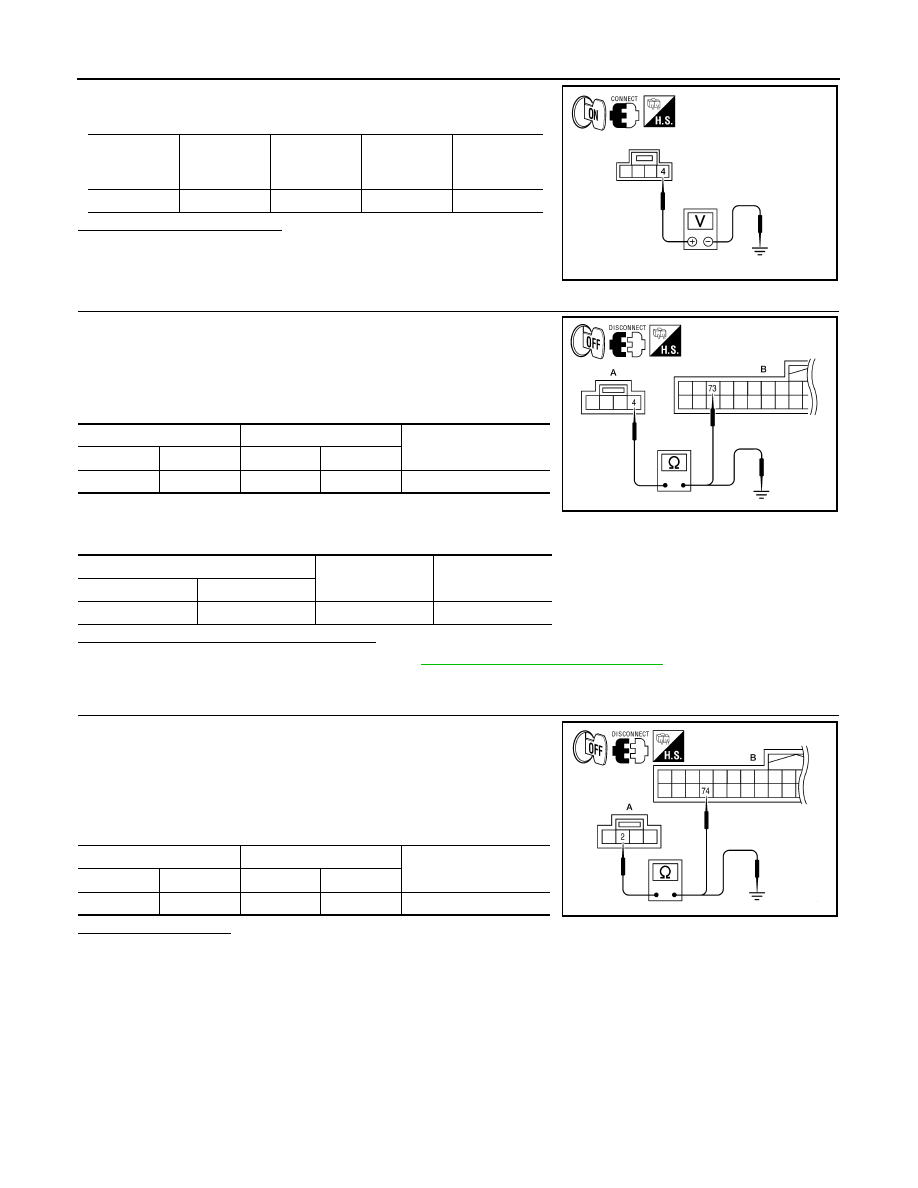
Check voltage between microphone harness connector R8 terminal
4 and ground.

Is approximately 5V present?

YES

>> GO TO 3

NO

>> GO TO 2

2.

CHECK POWER SUPPLY CIRCUIT (CONTINUITY)

1.

Turn ignition switch OFF.

2.

Disconnect microphone and AV control unit harness connectors.

3.

Check continuity between microphone harness connector R8
(A) terminal 4 and AV control unit harness connector M46 (B)
terminal 73. 

4.

Check continuity between microphone harness connector R8
(A) terminal 4 and ground. 

Are the continuity test results as specified?

YES

>> Replace the AV control unit. Refer to 

AV-423, "Removal and Installation"

.

NO

>> Repair harness or connector.

3.

CHECK GROUND CIRCUIT

1.

Turn ignition switch OFF.

2.

Disconnect microphone harness connector R8 and AV control
unit harness connector M46.

3.

Check continuity between microphone harness connector R8
(A) terminal 2 and AV control unit harness connector M46 (B)
terminal 74. 

Does continuity exist?

YES

>> Inspection End.

NO

>> Repair harness or connector.

Signal name

Connector 

No.

Terminal No.

Ignition 

switch posi-

tion

Value (Ap-

prox.)

MIC power

R8

4

ON

5V

WKIA5796E

A

B

Continuity

Connector

Terminal

Connector

Terminal

R8

4

M46

73

Yes

A

Continuity

Connector

Terminal

R8

4

Ground

No

ALNIA0548GB

A

B

Continuity

Connector

Terminal

Connector

Terminal

R8

2

M46

74

Yes

ALNIA0549GB

AV

RGB (R: RED) SIGNAL CIRCUIT

AV-345

< COMPONENT DIAGNOSIS >

[BOSE AUDIO WITH NAVIGATION]

C

D

E

F

G

H

I

J

K

L

M

B

A

O

P

RGB (R: RED) SIGNAL CIRCUIT

Description

INFOID:0000000001450618

Transmit the image displayed with audio control unit with RGB signal to the display unit.

Diagnosis Procedure

INFOID:0000000001450619

1.

CHECK CONTINUITY RGB (R: RED) SIGNAL CIRCUIT

1.

Turn ignition switch OFF.

2.

Disconnect display unit connector M93 and AV control unit con-
nector M43.

3.

Check continuity between display unit harness connector M93
(A) terminal 17 and AV control unit harness connector M43 (B)
terminal 21.

4.

Check continuity between display unit harness connector M93
(A) terminal 17 and ground.

Are the continuity results as specified?

YES

>> GO TO 2

NO

>> Repair harness or connector.

2.

CHECK RGB (R: RED) SIGNAL

1.

Connect display unit connector M93 and AV control unit connec-
tor M43.

2.

Turn ignition switch ON.

3.

Check signal between display unit harness connector M93 ter-
minal 17 and ground.

Are the voltage readings as specified?

YES

>> Replace display unit. Refer to 

AV-424, "Removal and Installation"

.

NO

>> Replace AV control unit. Refer to 

AV-423, "Removal and Installation"

.

A

B

Continuity

Connector

Terminal

Connector

Terminal

M93

17

M43

21

Yes

A

Continuity

Connector

Terminal

M93

17

Ground

No

ALNIA0409GB

(+)

(-)

Condition

Reference signal

Connector

Terminal

M93

17

Ground

Receive 
audio sig-
nal

ALNIA0383GB

SKIB2238J

AV-346

< COMPONENT DIAGNOSIS >

[BOSE AUDIO WITH NAVIGATION]

RGB (G: GREEN) SIGNAL CIRCUIT

RGB (G: GREEN) SIGNAL CIRCUIT

Description

INFOID:0000000001450620

Transmit the image displayed with AV control unit with RGB signal to the display unit.

Diagnosis Procedure

INFOID:0000000001450621

1.

CHECK CONTINUITY RGB (G: GREEN) SIGNAL CIRCUIT

1.

Turn ignition switch OFF.

2.

Disconnect display unit connector M93 and AV control unit con-
nector M43.

3.

Check continuity between display unit harness connector M93
(A) terminal 6 and AV control unit harness connector M43 (B)
terminal 22.

4.

Check continuity between display unit harness connector M93
(A) terminal 6 and ground.

Are the continuity results as specified?

YES

>> GO TO 2

NO

>> Repair harness or connector.

2.

CHECK RGB (G: GREEN) SIGNAL

1.

Connect display unit connector M93 and AV control unit connec-
tor M43.

2.

Turn ignition switch ON.

3.

Check signal between display unit harness connector M93 ter-
minal 6 and ground.

Are voltage readings as specified?

YES

>> Replace display unit. Refer to 

AV-424, "Removal and Installation"

.

NO

>> Replace AV control unit. Refer to 

AV-423, "Removal and Installation"

.

A

B

Continuity

Connector

Terminal

Connector

Terminal

M93

6

M43

22

Yes

A

Continuity

Connector

Terminal

M93

6

Ground

No

ALNIA0410GB

(+)

(-)

Condition

Reference signal

Connector

Terminal

M93

6

Ground

Receive 
audio sig-
nal

ALNIA0385GB

SKIB2236J

AV

RGB (B: BLUE) SIGNAL CIRCUIT

AV-347

< COMPONENT DIAGNOSIS >

[BOSE AUDIO WITH NAVIGATION]

C

D

E

F

G

H

I

J

K

L

M

B

A

O

P

RGB (B: BLUE) SIGNAL CIRCUIT

Description

INFOID:0000000001450622

Transmit the image displayed with AV control unit with RGB signal to the display unit.

Diagnosis Procedure

INFOID:0000000001450623

1.

CHECK CONTINUITY RGB (B: BLUE) SIGNAL CIRCUIT

1.

Turn ignition switch OFF.

2.

Disconnect display unit connector M93 and AV control unit con-
nector M43.

3.

Check continuity between display unit harness connector M93
(A) terminal 18 and AV control unit harness connector M43 (B)
terminal 23.

4.

Check continuity between display unit harness connector M93
(A) terminal 18 and ground.

Are continuity results as specified?

YES

>> GO TO 2

NO

>> Repair harness or connector.

2.

CHECK RGB (B: BLUE) SIGNAL

1.

Connect display unit connector M93 and AV control unit connec-
tor M43.

2.

Turn ignition switch ON.

3.

Check signal between display unit harness connector M93 ter-
minal 18 and ground.

Are voltage readings as specified?

YES

>> Replace display unit. Refer to 

AV-424, "Removal and Installation"

.

NO

>> Replace AV control unit. Refer to 

AV-423, "Removal and Installation"

.

A

B

Continuity

Connector

Terminal

Connector

Terminal

M93

18

M43

23

Yes

A

Continuity

Connector

Terminal

M93

18

Ground

No

ALNIA0411GB

(+)

(-)

Condition

Reference signal

Connector

Terminal

M93

18

Ground

Receive 
audio sig-
nal

ALNIA0387GB

SKIB2237J

AV-348

< COMPONENT DIAGNOSIS >

[BOSE AUDIO WITH NAVIGATION]

RGB SYNCHRONIZING SIGNAL CIRCUIT

RGB SYNCHRONIZING SIGNAL CIRCUIT

Description

INFOID:0000000001450624

Transmit the RGB synchronizing signal to the display unit so as to synchronize the RGB image displayed with
AV control unit.

Diagnosis Procedure

INFOID:0000000001450625

1.

CHECK CONTINUITY RGB SYNCHRONIZING SIGNAL CIRCUIT

1.

Turn ignition switch OFF.

2.

Disconnect display unit connector M93 and AV control unit con-
nector M43.

3.

Check continuity between display unit harness connector M93
(A) terminal 19 and AV control unit harness connector M43 (B)
terminal 25.

4.

Check continuity between display unit harness connector M93
(A) terminal 19 and ground.

Are continuity results as specified?

YES

>> GO TO 2

NO

>> Repair harness or connector.

2.

CHECK RGB SYNCHRONIZING SIGNAL

1.

Connect display unit connector M93 and AV control unit connec-
tor M43.

2.

Turn ignition switch ON.

3.

Check signal between display unit harness connector M93 ter-
minal 19 and ground.

Are voltage readings as specified?

YES

>> Replace display unit. Refer to 

AV-424, "Removal and Installation"

.

NO

>> Replace AV control unit. Refer to 

AV-423, "Removal and Installation"

.

A

B

Continuity

Connector

Terminal

Connector

Terminal

M93

19

M43

25

Yes

A

Continuity

Connector

Terminal

M93

19

Ground

No

ALNIA0412GB

(+)

(-)

Condition

Reference signal

Connector

Terminal

M93

19

Ground

Receive 
audio sig-
nal

ALNIA0389GB

SKIB3603E

AV

RGB AREA (YS) SIGNAL CIRCUIT

AV-349

< COMPONENT DIAGNOSIS >

[BOSE AUDIO WITH NAVIGATION]

C

D

E

F

G

H

I

J

K

L

M

B

A

O

P

RGB AREA (YS) SIGNAL CIRCUIT

Description

INFOID:0000000001450626

Transmits the display area of RGB image displayed by AV control unit with RGB area (YS) signal to display
unit.

Diagnosis Procedure

INFOID:0000000001450627

1.

CHECK CONTINUITY RGB AREA (YS) SIGNAL CIRCUIT

1.

Turn ignition switch OFF.

2.

Disconnect display unit connector M93 and AV control unit con-
nector M43.

3.

Check continuity between display unit harness connector M93
(A) terminal 9 and AV control unit harness connector M43 (B)
terminal 27.

4.

Check continuity between display unit harness connector M93
(A) terminal 9 and ground.

Are continuity results as specified?

YES

>> GO TO 2

NO

>> Repair harness or connector.

2.

CHECK RGB SYNCHRONIZING SIGNAL

1.

Connect display unit connector M93 and AV control unit connec-
tor M43.

2.

Turn ignition switch ON.

3.

Check signal between display unit harness connector M93 ter-
minal 9 and ground.

Are voltage readings as specified?

YES

>> Replace display unit. Refer to 

AV-424, "Removal and Installation"

.

NO

>> Replace AV control unit. Refer to 

AV-423, "Removal and Installation"

.

A

B

Continuity

Connector

Terminal

Connector

Terminal

M93

9

M43

27

Yes

A

Continuity

Connector

Terminal

M93

9

Ground

No

ALNIA0413GB

(+)

(-)

Condition

Reference signal

Connector

Terminal

M93

9

Ground

Receive 
audio sig-
nal

ALNIA0391GB

PKIB4948J

AV-350

< COMPONENT DIAGNOSIS >

[BOSE AUDIO WITH NAVIGATION]

HORIZONTAL SYNCHRONIZING (HP) SIGNAL CIRCUIT

HORIZONTAL SYNCHRONIZING (HP) SIGNAL CIRCUIT

Description

INFOID:0000000001450628

In composite image (AUX image, camera image), transmit the vertical synchronizing (VP) signal and horizon-
tal synchronizing (HP) signal from display unit to AV control unit so as to synchronize the RGB images dis-
played with AV control unit such as the image quality adjusting menu, etc.

Diagnosis Procedure

INFOID:0000000001450629

1.

CHECK CONTINUITY HORIZONTAL SYNCHRONIZING (HP) SIGNAL CIRCUIT

1.

Turn ignition switch OFF.

2.

Disconnect display unit connector M93 and AV control unit con-
nector M43.

3.

Check continuity between display unit harness connector M93
(A) terminal 8 and AV control unit harness connector M43 (B)
terminal 28.

4.

Check continuity between display unit harness connector M93
(A) terminal 8 and ground.

Are continuity results as specified?

YES

>> GO TO 2

NO

>> Repair harness or connector.

2.

CHECK HORIZONTAL SYNCHRONIZING (HP) SIGNAL

1.

Connect display unit connector M93 and AV control unit connec-
tor M43.

2.

Turn ignition switch ON.

3.

Check signal between display unit harness connector M93 ter-
minal 8 and ground.

Are voltage readings as specified?

YES

>> Replace AV control unit. Refer to 

AV-423, "Removal and Installation"

.

NO

>> Replace display unit. Refer to 

AV-424, "Removal and Installation"

.

A

B

Continuity

Connector

Terminal

Connector

Terminal

M93

8

M43

28

Yes

A

Continuity

Connector

Terminal

M93

8

Ground

No

ALNIA0414GB

(+)

(-)

Condition

Reference signal

Connector

Terminal

M93

8

Ground

Receive 
audio sig-
nal

ALNIA0396GB

SKIB3601E

AV

VERTICAL SYNCHRONIZING (VP) SIGNAL CIRCUIT

AV-351

< COMPONENT DIAGNOSIS >

[BOSE AUDIO WITH NAVIGATION]

C

D

E

F

G

H

I

J

K

L

M

B

A

O

P

VERTICAL SYNCHRONIZING (VP) SIGNAL CIRCUIT

Description

INFOID:0000000001450630

In composite image (AUX image, camera image), transmit the vertical synchronizing (VP) signal and horizon-
tal synchronizing (HP) signal from display unit to AV control unit so as to synchronize the RGB images dis-
played with AV control unit such as the image quality adjusting menu, etc.

Diagnosis Procedure

INFOID:0000000001450631

1.

CHECK CONTINUITY VERTICAL SINCHRONIZING (VP) SIGNAL CIRCUIT

1.

Turn ignition switch OFF.

2.

Disconnect display unit connector M93 and AV control unit con-
nector M43.

3.

Check continuity between display unit harness connector M93
(A) terminal 20 and AV control unit harness connector M43 (B)
terminal 29.

4.

Check continuity between display unit harness connector M93
(A) terminal 20 and ground.

Are continuity results as specified?

YES

>> GO TO 2

NO

>> Repair harness or connector.

2.

CHECK VERTICAL SINCHRONIZING (VP) SIGNAL

1.

Connect display unit connector M93 and AV control unit connec-
tor M43.

2.

Turn ignition switch ON.

3.

Check signal between display unit harness connector M93 ter-
minal 20 and ground.

Are voltage readings as specified?

YES

>> Replace AV control unit. Refer to 

AV-423, "Removal and Installation"

.

NO

>> Replace display unit. Refer to 

AV-424, "Removal and Installation"

.

A

B

Continuity

Connector

Terminal

Connector

Terminal

M93

20

M43

29

Yes

A

Continuity

Connector

Terminal

M93

20

Ground

No

ALNIA0415GB

(+)

(-)

Condition

Reference signal

Connector

Terminal

M93

20

Ground

Receive 
audio sig-
nal

ALNIA0393GB

SKIB3598E


Content      ..     61      62      63      64     ..