Nissan Pathfinder (2007 year). Manual - part 427


  Index      Manuals     Nissan Pathfinder (2007 year) - Service and Repair Manual


Search            copyright infringement  


Content      ..     425      426      427      428     ..


Nissan Pathfinder (2007 year). Manual - part 427


PLANETARY CARRIER

TF-297

[TX15B]

C

E

F

G

H

I

J

K

L

M

A

B

TF

2007 Pathfinder

Internal Gear

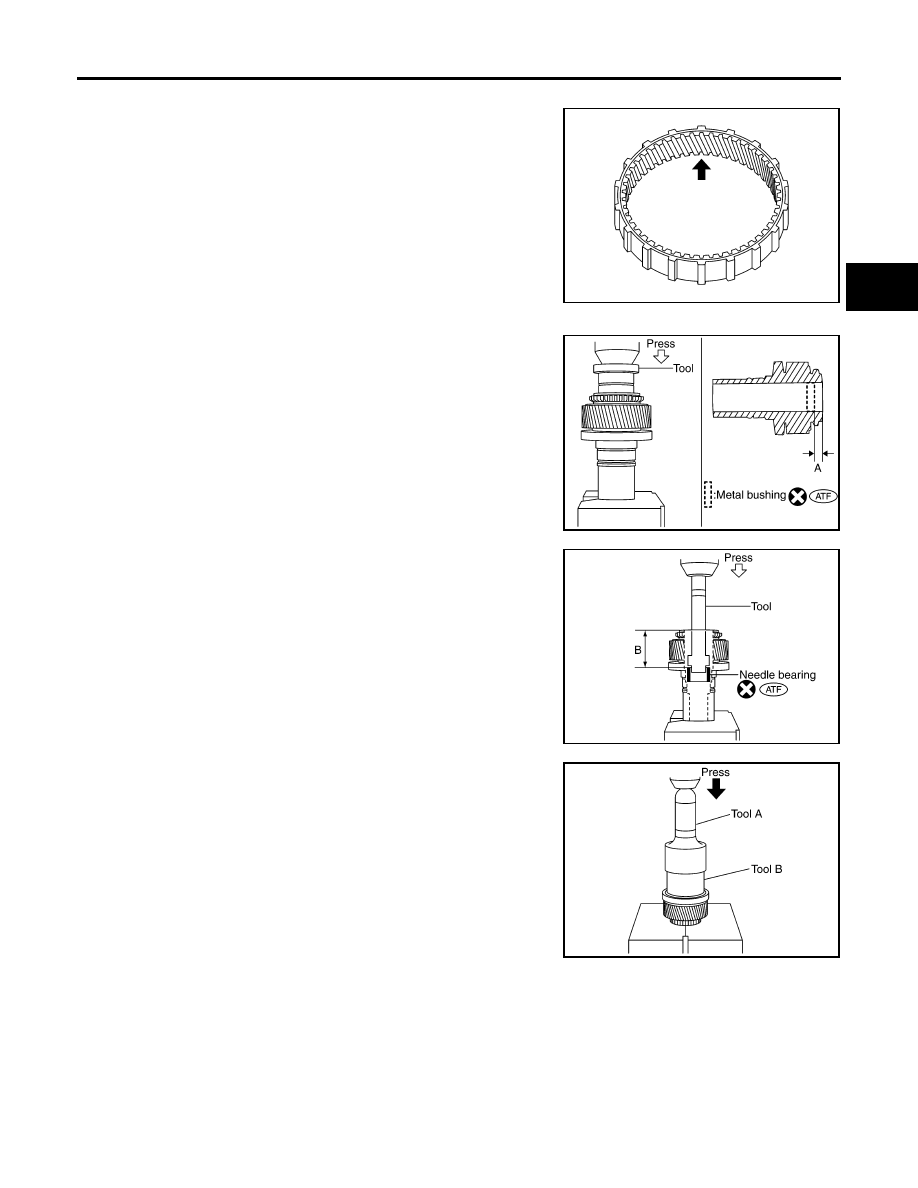
Check the internal gear teeth for damage, partial wear, dents or
other abnormality. If any is found, replace the internal gear with a
new one.

ASSEMBLY

1.

Apply ATF to the new metal bushing, then install the new metal
bushing until it becomes “Dimension A” using Tool.

CAUTION:

Do not reuse metal bushing.

2.

Apply ATF to the new needle bearing, then install the new nee-
dle bearing until it becomes “Dimension B” using Tool.

CAUTION:

Do not reuse needle bearing.

3.

Install the carrier bearing to the sun gear using Tools.

PDIA0157E

Tool number

: ST35300000 (

)

Dimension A

: 7.7 - 8.3mm (0.303 - 0.327in)

SDIA3189E

Tool number

: ST33220000 (

)

Dimension B

: 62.5 - 63.1mm (2.461 - 2.484in)

SDIA3190E

Tool number

A: ST30720000 (J-25405)

B: ST27863000 (

)

PDIA0149E

TF-298

[TX15B]

PLANETARY CARRIER

2007 Pathfinder

4.

Install the new snap ring to the sun gear assembly using suitable
tool.

CAUTION:

Do not reuse snap ring.

5.

Install the sun gear assembly to the planetary carrier assembly.

6.

Install the new snap ring to the planetary carrier assembly.

CAUTION:

Do not reuse snap ring.

SDIA2353E

SDIA2794E

FRONT DRIVE SHAFT

TF-299

[TX15B]

C

E

F

G

H

I

J

K

L

M

A

B

TF

2007 Pathfinder

FRONT DRIVE SHAFT

PFP:39100

Disassembly and Assembly

EDS00392

DISASSEMBLY

1.

Remove the front bearing using Tools.

2.

Remove the rear bearing using Tools.

INSPECTION AFTER DISASSEMBLY
Front Drive Shaft

Check the items below. If necessary, replace them with new ones.

Damage, peeling, dent, uneven wear and bending of the shaft.

Excessive wear, damage and peeling of the gear.

Bearing

Check the bearing for damage and rough rotation. If necessary,
replace the bearing with a new one.

Tool number

A: ST35300000 (

)

B: ST30021000 (J-22912-01)

SDIA2106E

Tool number

A: ST33710000 (

)

B: ST30021000 (J-22912-01)

PDIA0153E

PDIA0154E

MTF0041D

TF-300

[TX15B]

FRONT DRIVE SHAFT

2007 Pathfinder

ASSEMBLY

1.

Install the rear bearing using Tools.

2.

Install the front bearing using Tools.

Tool number

A: KV38100500 (

)

B: ST30901000 (J-26010-01)

PDIA0155E

Tool number

A: KV38100500 (

)

B: ST30901000 (J-26010-01)

PDIA0156E

SHIFT CONTROL

TF-301

[TX15B]

C

E

F

G

H

I

J

K

L

M

A

B

TF

2007 Pathfinder

SHIFT CONTROL

PFP:33167

Disassembly and Assembly

EDS00393

DISASSEMBLY

1.

Remove the snap ring.

2.

Remove the retaining pin. 

3.

Remove the drum cam from the control shift rod.

4.

Remove the retaining pin from the L-H shift rod.

5.

Remove the 2-4 shift bracket.

6.

Remove the retaining ring from the 2-4 shift fork using suitable
tool.

7.

Remove the fork guide collar and 2-4 shift fork spring from the 2-
4 shift fork.

INSPECTION AFTER DISASSEMBLY
Shift Fork

Measure the clearance between the shift fork and sleeve. If it is
out of specification, replace it with a new one.

PDIA0122E

PDIA0125E

WDIA0226E

Standard value

2-4

: Less than 0.46 mm (0.018 in)

L-H

: Less than 0.46 mm (0.018 in)

PDIA0134E

TF-302

[TX15B]

SHIFT CONTROL

2007 Pathfinder

Shift Rod and Fork Components

Check the working face of the shift rod and fork for wear, partial
wear, abrasion, bending and other abnormality. If any is found,
replace with a new one.

ASSEMBLY

1.

Install clevis pin and shift collar to L-H shift fork after assembling them.

CAUTION:

Use caution when installing L-H shift fork, clevis pin or shift collar.

2.

Install clevis pin and shift collar to 2-4 shift bracket after assembling them.

CAUTION:

Use caution when installing 2-4 shift bracket.

3.

Install guide fork collar and 2-4 shift fork spring to the 2-4 shift
fork, and then secure it with the new retaining ring.

CAUTION:

Do not reuse retaining ring.

Be careful with orientation.

4.

Install the 2-4shift bracket to the L-H shift rod.

5.

Install the new retaining pin evenly to the L-H shift rod.

CAUTION:

Do not reuse retaining pin.

6.

Install the drum cam to the control shift rod, and then secure it
with the new retaining pin.

CAUTION:

Do not reuse retaining pin.

7.

Install the new snap ring to the control shift rod.

CAUTION:

Do not reuse snap ring.

PDIA0135E

SDIA3391E

PDIA0125E

PDIA0122E

SERVICE DATA AND SPECIFICATIONS (SDS)

TF-303

[TX15B]

C

E

F

G

H

I

J

K

L

M

A

B

TF

2007 Pathfinder

SERVICE DATA AND SPECIFICATIONS (SDS)

PFP:00030

General Specifications

EDS00394

Inspection and Adjustment

EDS00395

PINION GEAR END PLAY

Unit: mm (in)

CLEARANCE BETWEEN SHIFT FORK AND SLEEVE

Unit: mm (in)

Applied model

VQ40DE

Transfer model

TX15B

Fluid capacity (Approx.)

 (US qt, lmp qt)

2.0 (2-1/8, 1-3/4)

Gear ratio

High

1.000

Low

2.625

Number of teeth

Planetary 
gear

Sun gear

56

Internal gear

91

Front drive sprocket

38

Front drive shaft

38

Item

Standard

Pinion gear end play

0.1 - 0.7 (0.004 - 0.028)

Item

Standard

2-4 shift fork to 2-4 sleeve

Less than 0.46 (0.018)

L-H shift fork to L-H sleeve

Less than 0.46 (0.018)

TF-304

[TX15B]

SERVICE DATA AND SPECIFICATIONS (SDS)

2007 Pathfinder


Content      ..     425      426      427      428     ..