Nissan Pathfinder (2007 year). Manual - part 347
REAR PROPELLER SHAFT
PR-11
C
E
F
G
H
I
J
K
L
M
A
B
PR
2007 Pathfinder
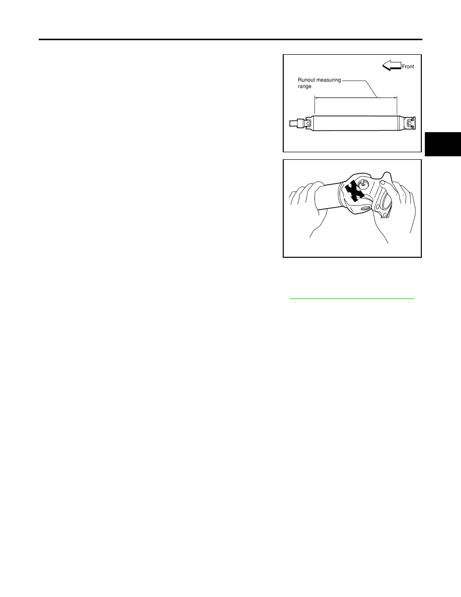
INSPECTION
●
Inspect the propeller shaft runout. If runout exceeds the limit,
replace the propeller shaft assembly.
●
While holding the flange yoke on one side, check axial play of
the joint as shown. If the journal axial play exceeds the specifi-
cation, repair or replace the journal parts.
●
Check the propeller shaft tube for dents or cracks. If damage is
detected, replace the propeller shaft assembly.
INSTALLATION
Installation is in the reverse order of removal.
●
After installation, check for vibration by driving the vehicle. Refer to
PR-3, "NVH Troubleshooting Chart"
.
CAUTION:
Do not reuse the bolts and nuts. Always install new ones.
Propeller shaft runout limit
2WD
: 1.02 mm (0.0402 in) or less
4WD
: 0.6 mm (0.024 in) or less
LDIA0121E
Journal axial play
: 0.02 mm (0.0008 in) or less
LDIA0117E