Nissan Pathfinder (2007 year). Manual - part 329
TROUBLE DIAGNOSIS
MTC-79
C
D
E
F
G
H
I
K
L
M
A
B
MTC
2007 Pathfinder
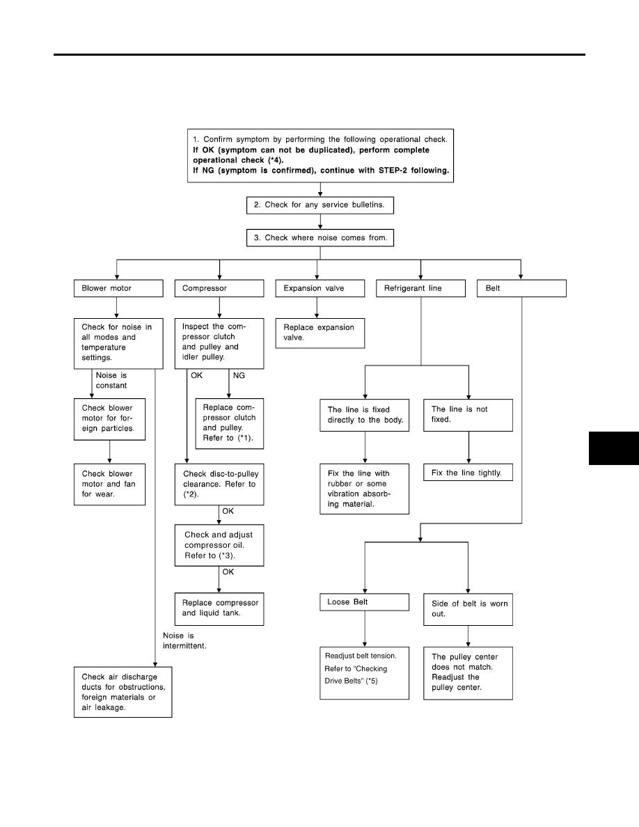
Noise
EJS004RU
SYMPTOM: Noise
INSPECTION FLOW
WJIA1972E
|
|
|
TROUBLE DIAGNOSIS MTC-79 C D E F G H I K L M A B MTC 2007 Pathfinder Noise EJS004RU SYMPTOM: Noise INSPECTION FLOW WJIA1972E |