Nissan Pathfinder (2007 year). Manual - part 314


  Index      Manuals     Nissan Pathfinder (2007 year) - Service and Repair Manual


Search            copyright infringement  


Content      ..     312      313      314      315     ..


Nissan Pathfinder (2007 year). Manual - part 314


OIL COOLER

LU-11

C

D

E

F

G

H

I

J

K

L

M

A

LU

2007 Pathfinder

OIL COOLER

PFP:21305

Removal and Installation

EBS00QCM

WARNING:

Be careful not to get burn yourself, as engine oil and engine coolant are hot.

REMOVAL

NOTE:
When removing oil cooler only, step 1 is unnecessary.

1.

Drain engine coolant from radiator and cylinder block. Refer to 

CO-9, "ENGINE COOLANT"

  and 

EM-108,

"DISASSEMBLY"

 .

NOTE:
Perform this step when removing water pipes.

2.

Remove oil filter. Refer to 

LU-10, "Changing Oil Filter"

 .

CAUTION:

Do not spill engine oil on drive belts.

3.

Disconnect water hoses from oil cooler.

When removing oil cooler only, pinching water hoses near oil cooler to prevent engine coolant spilling.

CAUTION:

Perform this step when engine is cold.

Do not spill engine coolant on drive belts.

4.

Remove connector bolt, and remove oil cooler.
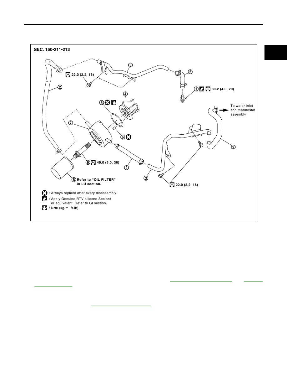
1.

Water connector

2.

Water hose

3.

Water pipe

4.

Oil pan (upper) front side

5.

O-ring

6.

Relief valve

7.

Oil cooler

8.

Oil filter

9.

Connector bolt

WBIA0572E

LU-12

OIL COOLER

2007 Pathfinder

CAUTION:

Do not spill engine oil to rubber parts such as drive belts and engine mounting insulator.

5.

Remove water pipes, as necessary.

INSPECTION AFTER REMOVAL
Oil Cooler

Check oil cooler for cracks. Check oil cooler for clogging by blowing through engine coolant inlet. If necessary,
replace oil cooler.

Relief Valve

Check relief valve for movement, cracks and breaks by pushing the ball. If replacement is necessary, remove
relief valve by prying it out using a suitable tool. Install a new relief valve in place by tapping it in.

INSTALLATION

Installation is in the reverse order of removal, paying attention to the following.

Make sure that no foreign objects are adhering to the installation planes of oil cooler and oil pan (upper).

Tighten connector bolt after aligning cutout on oil cooler with protrusion on oil pan (upper) side.

INSPECTION AFTER INSTALLATION

1.

Check the engine oil level and the engine coolant level, and add engine oil and engine coolant. Refer to

LU-7, "ENGINE OIL LEVEL"

  and 

CO-9, "ENGINE COOLANT"

 .

2.

Start engine, and make sure that there are no leaks of engine oil or engine coolant.

3.

Stop engine and wait for 10 minutes.

4.

Check the engine oil level and the engine coolant level again. Refer to 

LU-7, "ENGINE OIL LEVEL"

  and

CO-9, "ENGINE COOLANT"

 .

Connector bolt torque

: 49 N·m (5.0 kg-m, 36 ft-lb)

PBIC2825E

OIL PUMP

LU-13

C

D

E

F

G

H

I

J

K

L

M

A

LU

2007 Pathfinder

OIL PUMP

PFP:15010

Removal and Installation

EBS00QCN

REMOVAL

1.

Remove oil pans (lower and upper). Refer to 

EM-27, "Removal and Installation"

 .

2.

Remove front timing chain case and timing chain (primary). Refer to 

EM-55, "Removal and Installation"

 .

3.

Remove oil pump assembly.

INSTALLATION

Installation is in the reverse order of removal, paying attention to the following.

When installing, align crankshaft flat faces with inner rotor flat faces.

INSPECTION AFTER INSTALLATION

1.

Check the engine oil level. Refer to 

LU-7, "ENGINE OIL LEVEL"

 .

2.

Start engine, and check there are no leaks of engine oil.

3.

Stop engine and wait for 10 minutes.

4.

Check the engine oil level and add engine oil. Refer to 

LU-7, "ENGINE OIL LEVEL"

 .

Disassembly and Assembly

EBS00QCO

DISASSEMBLY

1.

Remove oil pump cover.

2.

Remove oil pump inner rotor and oil pump outer rotor from oil pump body.

3.

After removing regulator valve plug, remove regulator valve springs and regulator valve.

1.

Oil pump body

2.

Oil pump outer rotor

3.

Oil pump inner rotor

4.

Oil pump cover

5.

Regulator valve plug

6.

Regulator valve spring

7.

Regulator valve spring

8.

Regulator valve

PBIC2826E

LU-14

OIL PUMP

2007 Pathfinder

INSPECTION AFTER DISASSEMBLY
Oil Pump Clearance

Measure the clearance with feeler gauge.

Clearance between oil pump outer rotor and oil pump body
(position “1”)

Tip clearance between oil pump inner rotor and oil pump outer
rotor (position “2”)

Measure the clearance with feeler gauge and straightedge.

Side clearance between oil pump inner rotor and oil pump body
(position “3”)

Side clearance between oil pump outer rotor and oil pump body
(position “4”)

Calculate the clearance between oil pump inner rotor and oil pump body as follows:

OIL PUMP BODY INNER DIAMETER

Measure the inner diameter of oil pump body with inside
micrometer. (position “5”)

OIL PUMP INNER ROTOR OUTER DIAMETER

Measure the outer diameter of protruded portion of oil pump
inner rotor with micrometer. (position “6”)

OIL PUMP INNER ROTOR TO OIL PUMP BODY CLEARANCE

(Clearance) = (Oil pump body inner diameter) – (Oil pump inner rotor outer diameter)

If measured/calculated values are out of the standard, replace oil pump assembly.

Standard

: 0.120 - 0.195 mm (0.0047 - 0.0077 in)

Standard

: 0.06 - 0.16 mm (0.0024 - 0.0063 in)

PBIC2827E

Standard

: 0.030 - 0.070 mm (0.0012 - 0.0028 in)

Standard

: 0.05 - 0.09 mm (0.0020 - 0.0035 in)

PBIC2828E

PBIC0821E

Standard

: 0.045 - 0.091 mm (0.0018 - 0.0036 in)

OIL PUMP

LU-15

C

D

E

F

G

H

I

J

K

L

M

A

LU

2007 Pathfinder

Regulator Valve Clearance

(Clearance) = (Valve hole diameter) – (Regulator valve outer diame-
ter)

If the calculated value is out of the standard, replace oil pump
assembly.

CAUTION:

Coat regulator valve with engine oil.

Make sure that it falls smoothly into valve hole by its own
weight.

ASSEMBLY

Note the following, and assemble in the reverse order of disassembly.

Install oil pump inner rotor with the groove faced and oil pump
outer rotor with the punch mark to oil pump cover side.

Standard

: 0.025 - 0.070 mm (0.0010 - 0.0028 in)

PBIC2829E

PBIC2830E

LU-16

SERVICE DATA AND SPECIFICATIONS (SDS)

2007 Pathfinder

SERVICE DATA AND SPECIFICATIONS (SDS)

PFP:00030

Standard and Limit

EBS00QCP

OIL PRESSURE

*: Engine oil temperature at 80

°

C (176

°

F) 

OIL CAPACITY (APPROXIMATE)

Unit: 

 (US qt, Imp qt)

OIL PUMP

Unit: mm (in)

REGULATOR VALVE

Unit: mm (in)

Engine speed

rpm 

Approximate discharge pressure*

kPa (kg/cm

2

 , psi) 

Idle speed

More than 98 (1.0, 14)

2,000

More than 294 (3.0, 43) 

Drain and refill

With oil filter change

5.1 (5-3/8, 4-1/2)

Without oil filter change

4.8 (5-1/8, 4-1/4)

Dry engine (Overhaul)

6.3 (6-5/8, 5-1/2)               

Body to outer rotor radial clearance

0.120 - 0.195 (0.0047 - 0.0077)

Inner rotor to outer rotor tip clearance

0.06 - 0.16 (0.0024 - 0.0063)

Body to inner rotor side clearance

0.030 - 0.070 (0.0012 - 0.0028)

Body to outer rotor side clearance

0.05 - 0.09 (0.0020 - 0.0035)

Inner rotor to brazed portion of housing clearance

0.045 - 0.091 (0.0018 - 0.0036)

Regulator valve to oil pump body clearance

0.025 - 0.070 (0.0010 - 0.0028)

MA-1

MAINTENANCE

L  MAINTENANCE

CONTENTS

C

D

E

F

G

H

I

J

K

M

SECTION 

MA

A

B

MA

2007 Pathfinder

PRECAUTIONS .......................................................... 3

Precautions for Supplemental Restraint System 
(SRS) “AIR BAG” and “SEAT BELT PRE-TEN-
SIONER” .................................................................. 3

PREPARATION ........................................................... 4

Special Service Tools  ............................................... 4
Commercial Service Tool  ......................................... 4

GENERAL MAINTENANCE  ....................................... 5

General Maintenance ............................................... 5

PERIODIC MAINTENANCE  ....................................... 7

Introduction of Periodic Maintenance  ....................... 7
Schedule 1  ............................................................... 7

EMISSION CONTROL SYSTEM MAINTE-
NANCE .................................................................. 7
CHASSIS AND BODY MAINTENANCE  ............... 8

Schedule 2  ............................................................... 9

EMISSION CONTROL SYSTEM MAINTE-
NANCE .................................................................. 9
CHASSIS AND BODY MAINTENANCE  ............. 10

RECOMMENDED FLUIDS AND LUBRICANTS  .......11

Fluids and Lubricants  ..............................................11
SAE Viscosity Number  ........................................... 12

GASOLINE ENGINE OIL  .................................... 12
ANTI-FREEZE COOLANT MIXTURE RATIO  ..... 12

ENGINE MAINTENANCE  ......................................... 13

Checking Drive Belts  .............................................. 13

DRIVE BELT TENSION  ...................................... 13

Changing Engine Coolant  ...................................... 13

DRAINING ENGINE COOLANT  ......................... 13
REFILLING ENGINE COOLANT  ........................ 14
FLUSHING COOLING SYSTEM ......................... 16

Checking Fuel Lines ............................................... 16
Changing Fuel Filter ............................................... 16
Changing Engine Air Cleaner Filter ........................ 17

VISCOUS PAPER TYPE ..................................... 17

Changing Engine Oil  .............................................. 18
Changing Oil Filter  ................................................. 18
Changing Spark Plugs  ........................................... 19

REMOVAL ........................................................... 20
INSPECTION AFTER REMOVAL  ....................... 20

INSTALLATION ................................................... 20

Checking EVAP Vapor Lines  .................................. 20

CHASSIS AND BODY MAINTENANCE  ................... 21

Changing the In-cabin Microfilter  ............................ 21
Checking the Exhaust System ................................ 22
Checking the A/T Fluid (ATF)  ................................. 22
Changing the A/T Fluid (ATF)  ................................. 24
Checking Transfer Fluid  ......................................... 26

FLUID LEAKAGE AND FLUID LEVEL  ................ 26

Changing Transfer Fluid  ......................................... 26

DRAINING ........................................................... 26
FILLING ............................................................... 27

Checking Propeller Shaft ........................................ 27
Checking Front Final Drive Oil ................................ 28

OIL LEAKAGE AND OIL LEVEL  ......................... 28

Changing Front Final Drive Oil  ............................... 28

DRAINING ........................................................... 28
FILLING ............................................................... 28

Checking Rear Final Drive Oil  ................................ 28

OIL LEAKAGE AND OIL LEVEL  ......................... 28

Changing Rear Final Drive Oil ................................ 29

DRAINING ........................................................... 29
FILLING ............................................................... 29

Balancing Wheels ................................................... 29

WHEEL BALANCE REMOVAL ............................ 29
WHEEL BALANCE INSTALLATION AND 
ADJUSTMENT .................................................... 29

Tire Rotation  ........................................................... 31
Checking Brake Fluid Level and Leaks  .................. 31
Checking Brake Lines and Cables  ......................... 31
Checking Disc Brake  .............................................. 32

ROTOR ................................................................ 32
CALIPER ............................................................. 32
PAD ..................................................................... 32

Checking Steering Gear and Linkage  ..................... 32

STEERING GEAR  ............................................... 32
STEERING LINKAGE  ......................................... 32

Checking Power Steering Fluid and Lines .............. 33

CHECKING FLUID LEVEL  .................................. 33
CHECKING LINES  .............................................. 33


Content      ..     312      313      314      315     ..