Nissan Pathfinder (2007 year). Manual - part 293


  Index      Manuals     Nissan Pathfinder (2007 year) - Service and Repair Manual


Search            copyright infringement  


Content      ..     291      292      293      294     ..


Nissan Pathfinder (2007 year). Manual - part 293


TROUBLE DIAGNOSIS

LAN-75

[CAN]

C

D

E

F

G

H

I

J

L

M

A

B

LAN

2007 Pathfinder

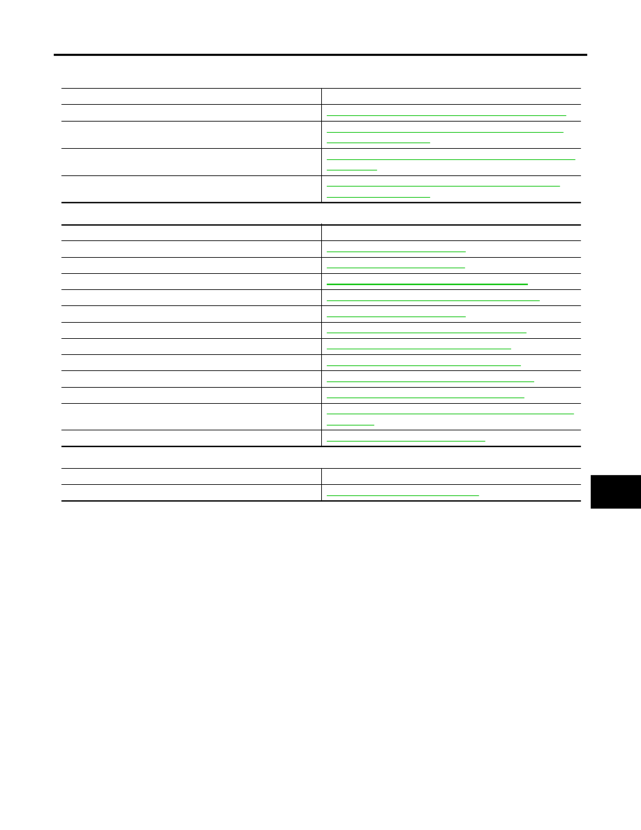
Malfunction Area Chart

UKS006I1

MAIN LINE

BRANCH LINE

SHORT CIRCUIT

Malfunction Area

Reference

Main line between TCM and data link connector

LAN-76, "Main Line Between TCM and Data Link Connector"

Main line between data link connector and ABS actuator and 
electric unit (control unit)

LAN-77, "Main Line Between Data Link Connector and ABS 
Actuator and Electric Unit"

Main line between data link connector and display control unit

LAN-78, "Main Line Between Data Link Connector and Display 
Control Unit"

Main line between display control unit and ABS actuator and 
electric unit (control unit)

LAN-79, "Main Line Between Display Control unit and ABS 
Actuator and Electric Unit"

Malfunction Area

Reference

ECM branch line circuit 

LAN-80, "ECM Branch Line Circuit"

TCM branch line circuit 

LAN-80, "TCM Branch Line Circuit"

Transfer control unit branch line circuit

LAN-81, "Transfer Control Unit Branch Line Circuit"

Driver seat control branch line circuit 

LAN-82, "Driver Seat Control Unit Branch Line Circuit"

BCM branch line circuit 

LAN-83, "BCM Branch Line Circuit"

Data link connector branch line circuit 

LAN-83, "Data Link Connector Branch Line Circuit"

Front air control branch line circuit

LAN-84, "Front Air Control Branch Line Circuit"

Combination meter branch line circuit 

LAN-85, "Combination Meter Branch Line Circuit"

Steering angle sensor branch line circuit 

LAN-85, "Steering Angle Sensor Branch Line Circuit"

Display control unit branch line circuit 

LAN-86, "Display Control Unit Branch Line Circuit"

ABS actuator and electric unit (control unit) branch line circuit 

LAN-87, "ABS Actuator and Electric Unit (Control Unit) Branch 
Line Circuit"

IPDM E/R branch line circuit 

LAN-87, "IPDM E/R Branch Line Circuit"

Malfunction Area

Reference

CAN communication circuit

LAN-88, "CAN Communication Circuit"

LAN-76

[CAN]

TROUBLE DIAGNOSIS

2007 Pathfinder

Main Line Between TCM and Data Link Connector

UKS006I2

INSPECTION PROCEDURE

1. 

CHECK CONNECTOR

1.

Turn the ignition switch OFF.

2.

Disconnect the battery cable from the negative terminal.

3.

Check the following terminals and connectors for damage, bend and loose connection (connector side
and harness side).

Harness connector F14

Harness connector E5

Harness connector E152

Harness connector M31

OK or NG

OK

>> GO TO 2.

NG

>> Repair the terminal and connector.

2. 

CHECK HARNESS CONTINUITY (OPEN CIRCUIT)

1.

Disconnect the following harness connectors.

A/T assembly connector

Harness connector F14 and E5

2.

Check the continuity between the A/T assembly harness connector and the harness connector.

OK or NG

OK

>> GO TO 3.

NG

>> Repair the main line between the A/T assembly and the harness connector F14.

3. 

CHECK HARNESS CONTINUITY (OPEN CIRCUIT)

1.

Disconnect the harness connectors E152 and M31.

2.

Check the continuity between harness connectors.

OK or NG

OK

>> GO TO 4.

NG

>> Repair the main line between the harness connector E5 and the harness connector E152.

A/T assembly harness connector

Harness connector

Continuity

Connector No.

Terminal No.

Connector No.

Terminal No.

F9

3

F14

2

Yes

8

3

Yes

Harness connector

Harness connector

Continuity

Connector No.

Terminal No.

Connector No.

Terminal No.

E5

2

E152

52G

Yes

3

51G

Yes

TROUBLE DIAGNOSIS

LAN-77

[CAN]

C

D

E

F

G

H

I

J

L

M

A

B

LAN

2007 Pathfinder

4. 

CHECK HARNESS CONTINUITY (OPEN CIRCUIT)

Check the continuity between the harness connector and the data link connector.

OK or NG

OK

>>

Present error: Check the following items again.

Decision of CAN system type.

Not received CONSULT-II data (SELECT SYSTEM, SELF-DIAG RESULTS, CAN DIAG SUP-
PORT MNTR).

Not copied from on-board diagnosis.

Procedure for detecting root cause.

Past error: Error was detected in the main line between the A/T assembly and the data link con-
nector.

NG

>> Repair the main line between the harness connector M31 and the data link connector.

Main Line Between Data Link Connector and ABS Actuator and Electric Unit

UKS006I3

INSPECTION PROCEDURE

1. 

CHECK CONNECTOR

1.

Turn the ignition switch OFF.

2.

Disconnect the battery cable from the negative terminal.

3.

Check the following terminals and connectors for damage, bend and loose connection (connector side
and harness side).

Harness connector M91

Harness connector E26

OK or NG

OK

>> GO TO 2.

NG

>> Repair the terminal and connector.

2. 

CHECK HARNESS CONTINUITY (OPEN CIRCUIT)

1.

Disconnect the harness connectors M91 and E26.

2.

Check the continuity between the data link connector and the harness connector.

OK or NG

OK

>> GO TO 3.

NG

>> Repair the main line between the data link connector and the harness connector M91.

Harness connector

Data link connector

Continuity

Connector No.

Terminal No.

Connector No.

Terminal No.

M31

52G

M22

6

Yes

51G

14

Yes

Data link connector

Harness connector

Continuity

Connector No.

Terminal No.

Connector No.

Terminal No.

M22

6

M91

11

Yes

14

10

Yes

LAN-78

[CAN]

TROUBLE DIAGNOSIS

2007 Pathfinder

3. 

CHECK HARNESS CONTINUITY (OPEN CIRCUIT)

1.

Disconnect the connector of ABS actuator and electric unit (control unit).

2.

Check the continuity between the harness connector and the ABS actuator and electric unit (control unit)
harness connector.

OK or NG

OK

>>

Present error: Check the following items again.

Decision of CAN system type.

Not received CONSULT-II data (SELECT SYSTEM, SELF-DIAG RESULTS, CAN DIAG SUP-
PORT MNTR).

Not copied from on-board diagnosis.

Procedure for detecting root cause.

Past error: Error was detected in the main line between the data link connector and the ABS
actuator and electric unit (control unit).

NG

>> Repair the main line between the harness connector E26 and the ABS actuator and electric unit

(control unit).

Main Line Between Data Link Connector and Display Control Unit

UKS006IJ

INSPECTION PROCEDURE

1. 

CHECK HARNESS CONTINUITY (OPEN CIRCUIT)

1.

Turn the ignition switch OFF.

2.

Disconnect the battery cable from the negative terminal.

3.

Disconnect ECM connector and display control unit connector.

4.

Check the continuity between the data link connector and the display control unit harness connector.

OK or NG

OK

>>

Present error: Check the following items again.

Decision of CAN system type.

Not received CONSULT-II data (SELECT SYSTEM, SELF-DIAG RESULTS, CAN DIAG SUP-
PORT MNTR).

Not copied from on-board diagnosis.

Procedure for detecting root cause.

Past error: Error was detected in the main line between the data link connector and the display
control unit.

NG

>> Repair the main line between the data link connector and the display control unit.

Harness connector

ABS actuator and electric unit (control unit)

harness connector

Continuity

Connector No.

Terminal No.

Connector No.

Terminal No.

E26

11

E125

11

Yes

10

15

Yes

Data link connector

Display control unit harness connector

Continuity

Connector No.

Terminal No.

Connector No.

Terminal No.

M22

6

M95

25

Yes

14

26

Yes

TROUBLE DIAGNOSIS

LAN-79

[CAN]

C

D

E

F

G

H

I

J

L

M

A

B

LAN

2007 Pathfinder

Main Line Between Display Control unit and ABS Actuator and Electric Unit

UKS006IK

INSPECTION PROCEDURE

1. 

CHECK CONNECTOR

1.

Turn the ignition switch OFF.

2.

Disconnect the battery cable from the negative terminal.

3.

Check the following terminals and connectors for damage, bend and loose connection (connector side
and harness side).

Harness connector M91

Harness connector E26

OK or NG

OK

>> GO TO 2.

NG

>> Repair the terminal and connector.

2. 

CHECK HARNESS CONTINUITY (OPEN CIRCUIT)

1.

Disconnect the following harness connectors.

Display control unit connector

Harness connector M91 and E26

2.

Check the continuity between the display control unit harness connector and the harness connector.

OK or NG

OK

>> GO TO 3.

NG

>> Repair the main line between the display control unit and the harness connector M91.

3. 

CHECK HARNESS CONTINUITY (OPEN CIRCUIT)

1.

Disconnect the connector of ABS actuator and electric unit (control unit).

2.

Check the continuity between the harness connector and the ABS actuator and electric unit (control unit)
harness connector.

OK or NG

OK

>>

Present error: Check the following items again.

Decision of CAN system type.

Not received CONSULT-II data (SELECT SYSTEM, SELF-DIAG RESULTS, CAN DIAG SUP-
PORT MNTR).

Not copied from on-board diagnosis.

Procedure for detecting root cause.

Past error: Error was detected in the main line between the display control unit and the ABS
actuator and electric unit (control unit).

NG

>> Repair the main line between the harness connector E26 and the ABS actuator and electric unit

(control unit).

Display control unit harness connector

Harness connector

Continuity

Connector No.

Terminal No.

Connector No.

Terminal No.

M95

25

M91

11

Yes

26

10

Yes

Harness connector

ABS actuator and electric unit (control unit)

harness connector

Continuity

Connector No.

Terminal No.

Connector No.

Terminal No.

E26

11

E125

11

Yes

10

15

Yes

LAN-80

[CAN]

TROUBLE DIAGNOSIS

2007 Pathfinder

ECM Branch Line Circuit

UKS006I4

INSPECTION PROCEDURE

1. 

CHECK CONNECTOR

1.

Turn the ignition switch OFF.

2.

Disconnect the battery cable from the negative terminal.

3.

Check the following terminals and connectors for damage, bend and loose connection (unit side and con-
nector side).

ECM connector

Harness connector E2

Harness connector F32

OK or NG

OK

>> GO TO 2.

NG

>> Repair the terminal and connector.

2. 

CHECK HARNESS FOR OPEN CIRCUIT

1.

Disconnect the connector of ECM.

2.

Check the resistance between the ECM harness connector terminals.

OK or NG

OK

>> GO TO 3.

NG

>> Repair the ECM branch line.

3. 

CHECK POWER SUPPLY AND GROUND CIRCUIT

Check the power supply and the ground circuit of the ECM. Refer to 

EC-146, "POWER SUPPLY AND

GROUND CIRCUIT"

 .

OK or NG

OK

>>

Present error: Replace the ECM. Refer to 

EC-76, "Procedure After Replacing ECM"

 .

Past error: Error was detected in the ECM branch line.

NG

>> Repair the power supply and the ground circuit.

TCM Branch Line Circuit

UKS006I5

INSPECTION PROCEDURE

1. 

CHECK CONNECTOR

1.

Turn the ignition switch OFF.

2.

Disconnect the battery cable from the negative terminal.

3.

Check the terminals and connectors of the A/T assembly for damage, bend and loose connection (unit
side and connector side).

OK or NG

OK

>> GO TO 2.

NG

>> Repair the terminal and connector.

ECM harness connector

Resistance (

)

Connector No.

Terminal No.

E16

94

86

Approx. 108 – 132

TROUBLE DIAGNOSIS

LAN-81

[CAN]

C

D

E

F

G

H

I

J

L

M

A

B

LAN

2007 Pathfinder

2. 

CHECK HARNESS FOR OPEN CIRCUIT

1.

Disconnect the connector of A/T assembly.

2.

Check the resistance between the A/T assembly harness connector terminals.

OK or NG

OK

>> GO TO 3.

NG

>> Repair the TCM branch line.

3. 

CHECK POWER SUPPLY AND GROUND CIRCUIT

Check the power supply and the ground circuit of the TCM. Refer to 

AT-167, "MAIN POWER SUPPLY AND

GROUND CIRCUIT"

 .

OK or NG

OK

>>

Present error: Replace the control valve with the TCM. Refer to 

AT-228, "CONTROL VALVE

WITH TCM REMOVAL AND INSTALLATION"

 .

Past error: Error was detected in the TCM branch line.

NG

>> Repair the power supply and the ground circuit.

Transfer Control Unit Branch Line Circuit

UKS006I6

INSPECTION PROCEDURE

1. 

CHECK CONNECTOR

1.

Turn the ignition switch OFF.

2.

Disconnect the battery cable from the negative terminal.

3.

Check the terminals and connectors of the transfer control unit for damage, bend and loose connection
(unit side and connector side).

OK or NG

OK

>> GO TO 2.

NG

>> Repair the terminal and connector.

2. 

CHECK HARNESS FOR OPEN CIRCUIT

1.

Disconnect the connector of transfer control unit.

2.

Check the resistance between the transfer control unit harness connector terminals.

Part time 4WD models

All-mode 4WD models

OK or NG

OK

>> GO TO 3.

NG

>> Repair the transfer control unit branch line.

A/T assembly harness connector

Resistance (

)

Connector No.

Terminal No.

F9

3

8

Approx. 54 – 66

Transfer control unit harness connector

Resistance (

)

Connector No.

Terminal No.

M152

1

2

Approx. 54 – 66

Transfer control unit harness connector

Resistance (

)

Connector No.

Terminal No.

M152

7

8

Approx. 54 – 66

LAN-82

[CAN]

TROUBLE DIAGNOSIS

2007 Pathfinder

3. 

CHECK POWER SUPPLY AND GROUND CIRCUIT

Check the power supply and the ground circuit of the transfer control unit. Refer to 

TF-222, "Power Supply Cir-

cuit For Transfer Control Unit"

  (Part time 4WD models) or 

TF-56, "Power Supply Circuit For Transfer Control

Unit"

  (All-mode 4WD models).

OK or NG

OK

>>

Present error: Replace the transfer control unit. Refer to 

TF-268, "TRANSFER CONTROL

UNIT"

  (Part time 4WD models) or 

TF-132, "TRANSFER CONTROL UNIT"

  (All-mode 4WD

models). 

Past error: Error was detected in the transfer control unit branch line.

NG

>> Repair the power supply and the ground circuit.

Driver Seat Control Unit Branch Line Circuit

UKS006IL

INSPECTION PROCEDURE

1. 

CHECK CONNECTOR

1.

Turn the ignition switch OFF.

2.

Disconnect the battery cable from the negative terminal.

3.

Check the following terminals and connectors for damage, bend and loose connection (unit side and con-
nector side).

Driver seat control unit connector

Harness connector P1

Harness connector B37

Harness connector B69

Harness connector M40

OK or NG

OK

>> GO TO 2.

NG

>> Repair the terminal and connector.

2. 

CHECK HARNESS FOR OPEN CIRCUIT

1.

Disconnect the connector of driver seat control unit.

2.

Check the resistance between the driver seat control unit harness connector terminals.

OK or NG

OK

>> GO TO 3.

NG

>> Repair the driver seat control unit branch line.

3. 

CHECK POWER SUPPLY AND GROUND CIRCUIT

Check the power supply and the ground circuit of the driver seat control unit. Refer to 

SE-30, "POWER SUP-

PLY AND GROUND CIRCUIT INSPECTION"

 .

OK or NG

OK

>>

Present error: Replace the driver seat control unit. Refer to 

SE-11, "Component Parts And Har-

ness Connector Location"

 . 

Past error: Error was detected in the driver seat control unit branch line.

NG

>> Repair the power supply and the ground circuit.

Driver seat control unit harness connector

Resistance (

)

Connector No.

Terminal No.

P2

3

19

Approx. 54 – 66


Content      ..     291      292      293      294     ..