Nissan Pathfinder (2007 year). Manual - part 241
CAMSHAFT
EM-85
C
D
E
F
G
H
I
J
K
L
M
A
EM
2007 Pathfinder
b.
Use feeler gauge, measure the clearance between valve lifter
and camshaft.
Valve clearance:
Unit: mm (in)
*: Approximately 80
°
C (176
°
F)
●
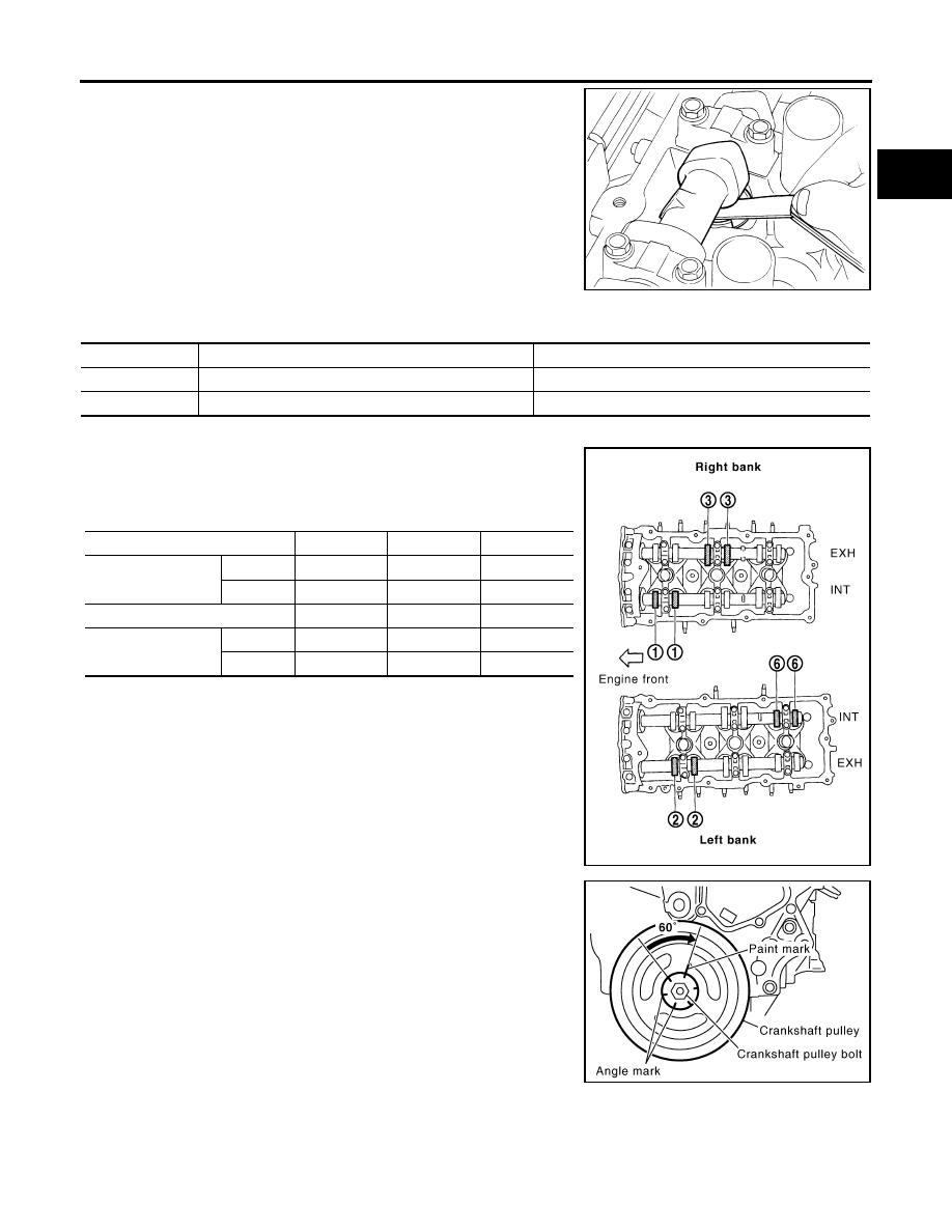
By referring to the figure, measure the valve clearances at
locations marked “
×
” as shown (locations indicated in the fig-
ure) with feeler gauge.
●
No. 1 cylinder at compression TDC
c.
Rotate crankshaft by 240
°
clockwise (when viewed from engine
front) to align No. 3 cylinder at TDC of its compression stroke.
NOTE:
Crankshaft pulley bolt flange has a stamped line every 60
°
. They
can be used as a guide to rotation angle.
SEM139D
Cold
Hot * (reference data)
Intake
0.26 - 0.34 (0.010 - 0.013)
0.304 - 0.416 (0.012 - 0.016)
Exhaust
0.29 - 0.37 (0.011 - 0.015)
0.308 - 0.432 (0.012 - 0.017)
Measuring position (right bank)
No. 1 CYL.
No. 3 CYL.
No. 5 CYL.
No. 1 cylinder at
compression TDC
EXH
×
INT
×
Measuring position (left bank)
No. 2 CYL.
No. 4 CYL.
No. 6 CYL.
No. 1 cylinder at
compression TDC
INT
×
EXH
×
PBIC2054E
PBIC2916E