Nissan Pathfinder (2007 year). Manual - part 195


  Index      Manuals     Nissan Pathfinder (2007 year) - Service and Repair Manual


Search            copyright infringement  


Content      ..     193      194      195      196     ..


Nissan Pathfinder (2007 year). Manual - part 195


DTC P0453 EVAP CONTROL SYSTEM PRESSURE SENSOR

EC-427

C

D

E

F

G

H

I

J

K

L

M

A

EC

2007 Pathfinder

DTC P0453 EVAP CONTROL SYSTEM PRESSURE SENSOR

PFP:25085

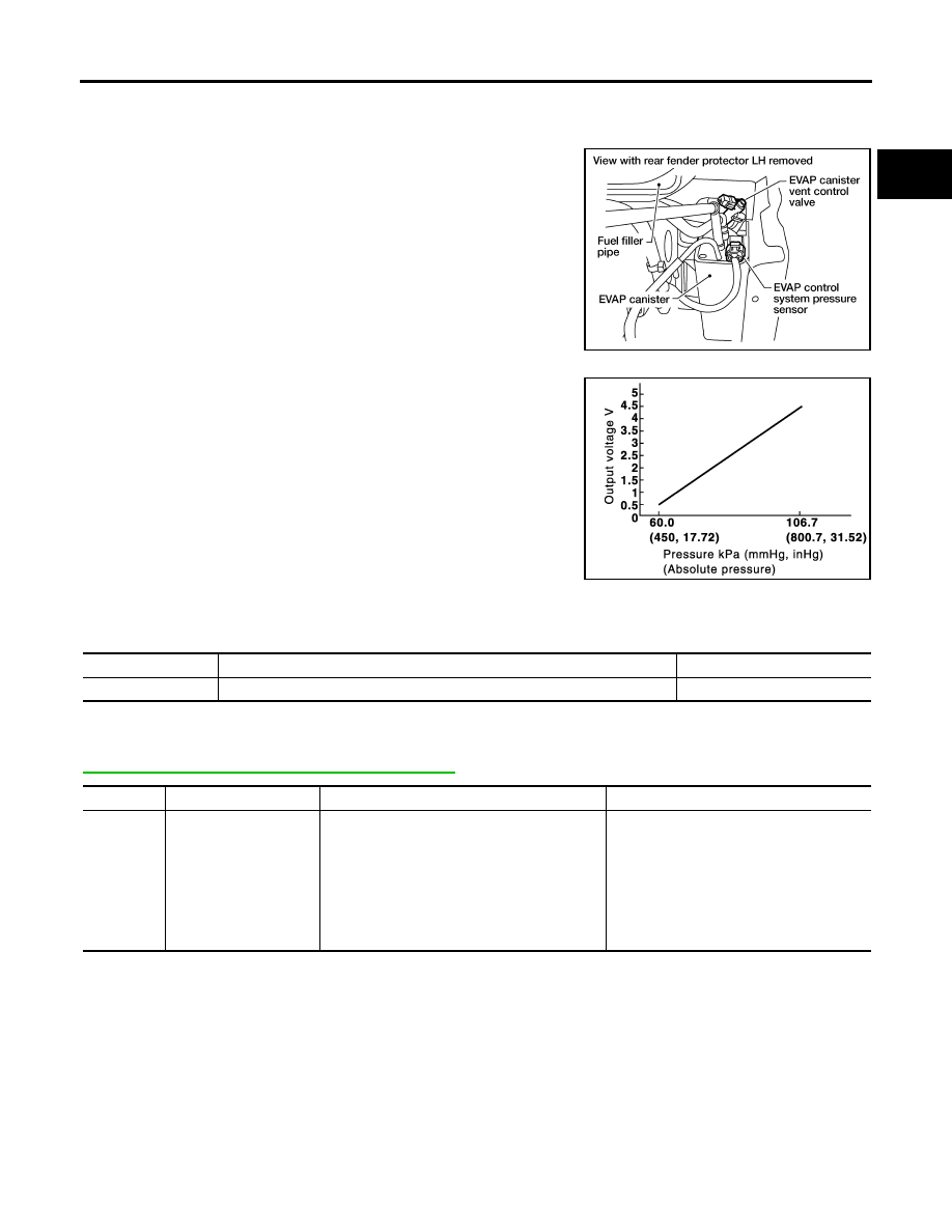
Component Description

UBS00K9Y

The EVAP control system pressure sensor detects pressure in the
purge line. The sensor output voltage to the ECM increases as pres-
sure increases.

CONSULT-II Reference Value in Data Monitor Mode

UBS00K9Z

Specification data are reference values.

On Board Diagnosis Logic

UBS00KA0

If DTC P0453 is displayed with DTC P0643, first perform the trouble diagnosis for DTC P0643. Refer to

EC-475, "DTC P0643 SENSOR POWER SUPPLY"

  .

BBIA0551E

PBIB1207E

MONITOR ITEM

CONDITION

SPECIFICATION

EVAP SYS PRES

Ignition switch: ON

Approx. 1.8 - 4.8V

DTC No.

Trouble diagnosis name

DTC detecting condition

Possible cause

P0453
0453

EVAP control system 
pressure sensor high 
input

An excessively high voltage from the sensor is 
sent to ECM.

Harness or connectors
(The sensor circuit is open or shorted.)

EVAP control system pressure sensor

EVAP canister vent control valve

EVAP canister

Rubber hose from EVAP canister vent 
control valve to vehicle frame

EC-428

DTC P0453 EVAP CONTROL SYSTEM PRESSURE SENSOR

2007 Pathfinder

DTC Confirmation Procedure

UBS00KA1

NOTE:
If DTC Confirmation Procedure has been previously conducted, always turn ignition switch OFF and wait at
least 10 seconds before conducting the next test.
TESTING CONDITION:
Always perform test at a temperature of 5

°

C (41

°

F) or more.

 WITH CONSULT-II

1.

Start engine and warm it up to normal operating temperature.

2.

Turn ignition switch OFF and wait at least 10 seconds.

3.

Turn ignition switch ON.

4.

Select “DATA MONITOR” mode with CONSULT-II.

5.

Make sure that “FUEL T/TMP SE” is more than 0

°

C (32

°

F).

6.

Start engine and wait at least 20 seconds.

7.

If 1st trip DTC is detected, go to 

EC-430, "Diagnostic Procedure"

.

 WITH GST

1.

Start engine and warm it up to normal operating temperature.

2.

Check that voltage between ECM terminal 107 (Fuel tank tem-
perature sensor signal) and ground is less than 4.2V.

3.

Turn ignition switch OFF and wait at least 10 seconds.

4.

Start engine and wait at least 20 seconds.

5.

Select Service $07 with GST.
If 1st trip DTC is detected, go to 

EC-430, "Diagnostic Procedure"

.

SEF194Y

PBIB1110E

DTC P0453 EVAP CONTROL SYSTEM PRESSURE SENSOR

EC-429

C

D

E

F

G

H

I

J

K

L

M

A

EC

2007 Pathfinder

Wiring Diagram

UBS00KA2

BBWA1756E

EC-430

DTC P0453 EVAP CONTROL SYSTEM PRESSURE SENSOR

2007 Pathfinder

Specification data are reference values and are measured between each terminal and ground.

CAUTION:

Do not use ECM ground terminals when measuring input/output voltage. Doing so may result in dam-
age to the ECM's transistor. Use a ground other than ECM terminals, such as the ground.

Diagnostic Procedure

UBS00KA3

1. 

CHECK GROUND CONNECTIONS

1.

Turn ignition switch OFF.

2.

Loosen and retighten three ground screws on the body. Refer to 

EC-153, "Ground Inspection"

  .

OK or NG

OK

>> GO TO 2.

NG

>> Repair or replace ground connections.

2. 

CHECK CONNECTOR

1.

Disconnect EVAP control system pressure sensor harness con-
nector.

2.

Check sensor harness connector for water.

OK or NG

OK

>> GO TO 3.

NG

>> Repair or replace harness connector.

TER-

MINAL 

NO.

WIRE 

COLOR

ITEM

CONDITION

DATA (DC Voltage)

32

W

EVAP control system pres-
sure sensor

[Ignition switch: ON]

Approximately 1.8 - 4.8V

48

SB

Sensor power supply
(EVAP control system pres-
sure sensor)

[Ignition switch: ON]

Approximately 5V

67

B

Sensor ground

[Engine is running]

Warm-up condition

Idle speed

Approximately 0V

BBIA0539E

Water should not exist.

BBIA0551E

DTC P0453 EVAP CONTROL SYSTEM PRESSURE SENSOR

EC-431

C

D

E

F

G

H

I

J

K

L

M

A

EC

2007 Pathfinder

3. 

CHECK EVAP CONTROL SYSTEM PRESSURE SENSOR POWER SUPPLY CIRCUIT

1.

Turn ignition switch ON.

2.

Check voltage between EVAP control system pressure sensor
terminal 3 and ground with CONSULT-II or tester.

OK or NG

OK

>> GO TO 5.

NG

>> GO TO 4.

4. 

DETECT MALFUNCTIONING PART

Check the following.

Harness connectors C1, E41

Harness connectors E5, F14

Harness for open or short between EVAP control system pressure sensor and ECM

>> Repair open circuit or short to ground or short to power in harness or connectors.

5. 

CHECK EVAP CONTROL SYSTEM PRESSURE SENSOR GROUND CIRCUIT FOR OPEN AND 

SHORT

1.

Turn ignition switch OFF.

2.

Disconnect ECM harness connector.

3.

Check harness continuity between EVAP control system pressure sensor terminal 1 and ECM terminal
67.
Refer to Wiring Diagram.

4.

Also check harness for short to ground and short to power.

OK or NG

OK

>> GO TO 7.

NG

>> GO TO 6.

6. 

DETECT MALFUNCTIONING PART

Check the following.

Harness connectors C1, E41

Harness connectors E5, F14

Harness for open or short between EVAP control system pressure sensor and ECM

>> Repair open circuit or short to ground or short to power in harness or connectors.

Voltage: Approximately 5V

PBIB0138E

Continuity should exist.

EC-432

DTC P0453 EVAP CONTROL SYSTEM PRESSURE SENSOR

2007 Pathfinder

7. 

CHECK EVAP CONTROL SYSTEM PRESSURE SENSOR INPUT SIGNAL CIRCUIT FOR OPEN AND 

SHORT

1.

Check harness continuity between ECM terminal 32 and EVAP control system pressure sensor terminal
2. 
Refer to Wiring Diagram.

2.

Also check harness for short to ground and short to power.

OK or NG

OK

>> GO TO 9.

NG

>> GO TO 8.

8. 

DETECT MALFUNCTIONING PART

Check the following.

Harness connectors C1, E41

Harness connectors E5, F14

Harness for open or short between EVAP control system pressure sensor and ECM

>> Repair open circuit or short to ground or short to power in harness or connectors.

9. 

CHECK RUBBER TUBE

1.

Disconnect rubber tube connected to EVAP canister vent control valve.

2.

Check the rubber tube for clogging, vent and kinked.

OK or NG

OK

>> GO TO 10.

NG

>> Clean the rubber tube using an air blower, repair or replace rubber tube.

10. 

CHECK EVAP CANISTER VENT CONTROL VALVE

Refer to 

EC-410, "Component Inspection"

  .

OK or NG

OK

>> GO TO 11.

NG

>> Replace EVAP canister vent control valve.

11. 

CHECK EVAP CONTROL SYSTEM PRESSURE SENSOR

Refer to 

EC-434, "Component Inspection"

  .

OK or NG

OK

>> GO TO 12.

NG

>> Replace EVAP control system pressure sensor.

Continuity should exist.

DTC P0453 EVAP CONTROL SYSTEM PRESSURE SENSOR

EC-433

C

D

E

F

G

H

I

J

K

L

M

A

EC

2007 Pathfinder

12. 

CHECK IF EVAP CANISTER SATURATED WITH WATER

1.

Remove EVAP canister with EVAP canister vent control valve and EVAP control system pressure sensor
attached.

2.

Check if water will drain from the EVAP canister.

Yes or No

Yes

>> GO TO 13.

No

>> GO TO 15.

13. 

CHECK EVAP CANISTER

Weigh the EVAP canister with the EVAP canister vent control valve and EVAP control system pressure sensor
attached.
The weight should be less than 2.0 kg (4.4 lb).

OK or NG

OK

>> GO TO 15.

NG

>> GO TO 14.

14. 

DETECT MALFUNCTIONING PART

Check the following.

EVAP canister for damage

EVAP hose between EVAP canister and vehicle frame for clogging or poor connection

>> Repair hose or replace EVAP canister.

15. 

CHECK INTERMITTENT INCIDENT

Refer to 

EC-145, "TROUBLE DIAGNOSIS FOR INTERMITTENT INCIDENT"

  .

>> INSPECTION END

BBIA0558E

EC-434

DTC P0453 EVAP CONTROL SYSTEM PRESSURE SENSOR

2007 Pathfinder

Component Inspection

UBS00KA4

EVAP CONTROL SYSTEM PRESSURE SENSOR

1.

Remove EVAP control system pressure sensor with its harness connector connected from EVAP canister.
Always replace O-ring with a new one.

2.

Install a vacuum pump to EVAP control system pressure sensor.

3.

Turn ignition switch ON and check output voltage between ECM
terminal 32 and ground under the following conditions.

CAUTION:

Always calibrate the vacuum pump gauge when using it.

Do not apply below -93.3 kPa (-700 mmHg, -27.56 inHg) or
pressure over 101.3 kPa (760 mmHg, 29.92 inHg).

4.

If NG, replace EVAP control system pressure sensor.

Applied vacuum kPa

(mmHg, inHg)

Voltage V

Not applied

1.8 - 4.8

-26.7 (-200, -7.87)

2.1 to 2.5V lower than above value

PBIB1173E


Content      ..     193      194      195      196     ..