Nissan Pathfinder (2006 year). Manual - part 371


  Index      Manuals     Nissan Pathfinder (2006 year) - Service and Repair Manual


Search            copyright infringement  


Content      ..     369      370      371      372     ..


Nissan Pathfinder (2006 year). Manual - part 371


BATTERY

SC-5

C

D

E

F

G

H

I

J

L

M

A

B

SC

2006 Pathfinder

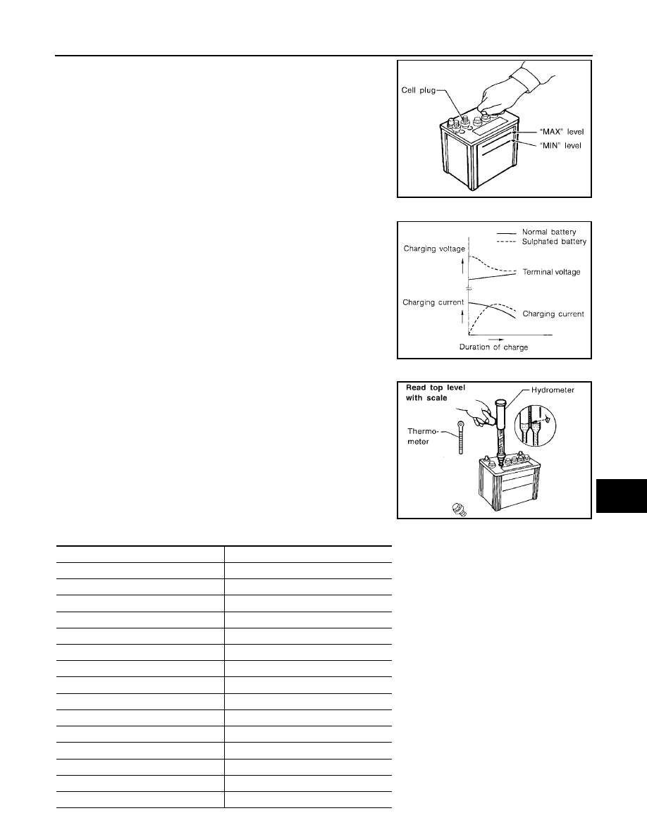
Remove the cell plug using a suitable tool.

Add distilled water up to the MAX level.

Sulfation

A battery will be completely discharged if it is left unattended
for a long time and the specific gravity will become less than
1.100. This may result in sulfation of the cell plates.
To determine if a battery has been sulfated, note its voltage and
current when charging it. As shown in the figure, less current
and higher voltage are observed in the initial stage of charging
sulfated batteries.
A sulfated battery may sometimes be brought back into service
by means of a long, slow charge, 12 hours or more, followed by
a battery capacity test.

SPECIFIC GRAVITY CHECK

1.

Read hydrometer and thermometer indications at eye level.

2.

Use the following chart to correct your hydrometer reading
according to electrolyte temperature.

Hydrometer Temperature Correction

MEL043F

PKIA2353E

MEL042FA

Battery electrolyte temperature 

°

C (

°

F)

Add to specific gravity reading

71 (160)

0.032

66 (150)

0.028

60 (140)

0.024

54 (130)

0.020

49 (120)

0.016

43 (110)

0.012

38 (100)

0.008

32 (90)

0.004

27 (80)

0

21 (70)

0.004

16 (60)

0.008

10 (50)

0.012

4 (40)

0.016

1 (30)

0.020

7 (20)

0.024

SC-6

BATTERY

2006 Pathfinder

CHARGING THE BATTERY

CAUTION:

Do not “quick charge” a fully discharged battery.

Keep the battery away from open flame while it is being charged.

When connecting the charger, connect the leads first, then turn on the charger. Do not turn on the
charger first, as this may cause a spark.

If battery electrolyte temperature rises above 55

°

C (131

°

F), stop charging. Always charge battery

at a temperature below 55

°

C (131

°

F).

Charging Rates

Do not charge at more than 50 ampere rate.

NOTE:
The ammeter reading on your battery charger will automatically decrease as the battery charges. This indi-
cates that the voltage of the battery is increasing normally as the state of charge improves. The charging amps
indicated above refer to initial charge rate.

If, after charging, the specific gravity of any two cells varies more than 0.050, the battery should be
replaced.

Trouble Diagnoses with Battery/Starting/Charging System Tester

EKS00FTI

CAUTION:

When working with batteries, always wear appropriate eye protection.
NOTE:

To ensure a complete and thorough diagnosis, the battery, starter and generator test segments must be
done as a set from start to finish.

If battery surface charge is detected while testing, the tester will prompt you to turn on the headlights to
remove the surface charge.

If necessary, the tester will prompt you to determine if the battery temperature is above or below 0

°

C

(32

°

F). Choose the appropriate selection by pressing the up or down arrow button, then press “ENTER” to

make the selection.

12 (10)

0.028

18 (0)

0.032

Corrected specific gravity

Approximate charge condition

1.260 - 1.280

Fully charged

1.230 - 1.250

3/4 charged

1.200 - 1.220

1/2 charged

1.170 - 1.190

1/4 charged

1.140 - 1.160

Almost discharged

1.110 - 1.130

Completely discharged

Battery electrolyte temperature 

°

C (

°

F)

Add to specific gravity reading

Amps

Time

50

1 hour

25

2 hours

10

5 hours

5

10 hours

BATTERY

SC-7

C

D

E

F

G

H

I

J

L

M

A

B

SC

2006 Pathfinder

1.

Turn off all loads on the vehicle electrical system. Clean or repair
as necessary.

2.

Visually inspect the battery, battery terminals and cable ends
with ignition switch in “OFF” position.

NOTE:
The contact surface between the battery terminals, cable ends
and tester leads must be clean for a valid test. A poor connec-
tion will prevent testing and a “CHECK CONNECTION” mes-
sage will appear during the test procedures. If this occurs, clean
the battery post and terminals, reconnect them and restart the
test.

3.

Connect the red tester lead clamp to the positive battery termi-
nal, and the black to the negative terminal.

4.

The tester will turn on automatically. Using the arrow keys,
select “IN-VEHICLE” on the tester and then press the “ENTER”
key.

5.

Locate the battery type and rating stamped or written on the top
case of the battery to be tested.

NOTE:
The battery rating will be either of the following:

CCA: Cold Cranking Amps (490 CCA, 550 CCA, etc.)

JIS: Japanese Industrial Standard.

When using the Battery Tester use the CCA rating only.

The tester requires the CCA rating for the battery be entered
exactly as it is written or stamped on the battery.

(U.S. market) Refer to the latest "Battery Testing" Technical
Service Bulletin (TSB) for a chart which contains these ratings
listed by vehicle.

You must not use the JIS rating.

6.

Using the arrow and “ENTER” keys alternately, select the battery type and rating.

NOTE:
The tester lists five choices; CCA, JIS, IEC, DIN, and EN. Only use CCA.

7.

Press “ENTER” to begin the test. Diagnosis results are dis-
played on the tester. Refer to 

SC-8, "DIAGNOSTIC RESULT

ITEM CHART"

 .

SEL404X

SEL405X

WKIA4228E

SEL407X

SC-8

BATTERY

2006 Pathfinder

8.

Press “ENTER”, then test output code is displayed. Record the
test output code on the repair order.

9.

Toggle back to the “DIAGNOSTIC SCREEN” for test results.

NOTE:

If necessary, the tester will ask the user to determine if the
battery has just been charged. Choose the appropriate selec-
tion by pressing the up or down arrow button and then press
the “ENTER” button to make the selection.

When testing a battery installed in a vehicle that has recently
been driven, select “BEFORE CHARGE”.

If the battery has just been slow charged due to a “CHARGE
& RETEST” decision by the tester, and the tester asks the user “BEFORE CHARGE/AFTER
CHARGE”, select “AFTER CHARGE”.

DIAGNOSTIC RESULT ITEM CHART

SEL576X

Diagnostic item

Service procedure

GOOD BATTERY

Battery is OK. Refer to 

SC-6, "Trouble Diagnoses with Battery/Starting/Charging System 

Tester"

 .

REPLACE BATTERY

Replace battery.
Before replacing battery, clean the battery cable clamps and battery posts. Perform battery 
test again with Battery/Starting/Charging system tester. If second test result is “Replace Bat-
tery”, then do so. Perform battery test again to confirm repair.

BAD CELL-REPLACE

Replace the battery. Perform battery test again with Battery/Starting/Charging system tester 
to confirm repair.

GOOD-RECHARGE

Perform the slow battery charging procedure. (Initial rate of charge is 10A for 12 hours.) Per-
form battery test again with Battery/Starting/Charging system tester.

CHARGE & RETEST

Perform the slow battery charging. (Initial rate of charge is 10A for 12 hours.)
Perform battery test again with Battery/Starting/Charging system tester to confirm repair.

NOTE:
If the tester asks the user “BEFORE CHARGE/AFTER CHARGE”, select “AFTER 
CHARGE”.

BATTERY

SC-9

C

D

E

F

G

H

I

J

L

M

A

B

SC

2006 Pathfinder

Removal and Installation 

EKS00FTJ

REMOVAL

1.

Disconnect both negative and positive battery terminal.

CAUTION:

Remove negative battery terminal first.

2.

Remove battery clamp nuts and battery clamp.

3.

Remove battery.

INSTALLATION

Installation is in the reverse order of removal.

CAUTION:

Install positive battery terminal first.

WKIA3188E

Battery clamp bolt

: 3.4 N·m (0.35 kg-m, 30 in-lb)

Battery terminal nut

: 3.4 N·m (0.35 kg-m, 30 in-lb)

SC-10

STARTING SYSTEM

2006 Pathfinder

STARTING SYSTEM

PFP:23300

System Description

EKS00FTK

Power is supplied at all times:

to starter motor terminal 2 and

through 40A fusible link (letter j , located in the fuse and fusible link box)

to ignition switch terminal B.

With the ignition switch in the START position, power is supplied:

from ignition switch terminal ST

to IPDM E/R terminal 21.

With the ignition switch in the ON or START position, power is supplied to IPDM E/R (intelligent power distribu-
tion module engine room) CPU.
With the selector lever in the P or N position, power is supplied:

through A/T assembly terminal 9

to IPDM E/R terminal 48.

Ground is supplied at all times:

to IPDM E/R terminals 38 and 59

from body grounds E9, E15 and E24.

Provided that the IPDM E/R receives a starter relay request ON signal from the BCM over the CAN lines, the
IPDM E/R grounds the starter relay and power is supplied:

from terminal 19 of the IPDM E/R

to terminal 1 of the starter motor.

The starter motor plunger closes and provides a closed circuit between the battery and the starter motor. The
starter motor is grounded to the cylinder block. With power and ground supplied, the starter motor operates.

STARTING SYSTEM

SC-11

C

D

E

F

G

H

I

J

L

M

A

B

SC

2006 Pathfinder

Wiring Diagram — START —

EKS00FTL

WKWA4247E

SC-12

STARTING SYSTEM

2006 Pathfinder

WKWA4248E


Content      ..     369      370      371      372     ..