Nissan Pathfinder (2006 year). Manual - part 322


  Index      Manuals     Nissan Pathfinder (2006 year) - Service and Repair Manual


Search            copyright infringement  


Content      ..     320      321      322      323     ..


Nissan Pathfinder (2006 year). Manual - part 322


INTERIOR ROOM LAMP

LT-131

C

D

E

F

G

H

I

J

L

M

A

B

LT

2006 Pathfinder

Personal Lamp Control Does Not Operate (Room/Map Lamps Operate)

EKS00FXH

1. 

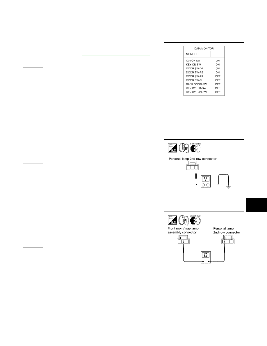
CHECK EACH DOOR SWITCH

Select "BCM" on CONSULT-II. With "INT LAMP" data monitor, make
sure switches listed in display item list turn ON-OFF linked with
switch operation. Refer to 

LT-117, "SWITCH OPERATION"

  for

switches and their function.
OK or NG

OK

>> GO TO 2.

NG

>> Inspect malfunctioning door switch.

2. 

CHECK PERSONAL LAMP OUTPUT 

1.

Turn ignition switch OFF.

2.

Confirm lamp switch is in the DOOR position.

3.

Disconnect personal lamp 2nd row connector.

4.

Open any door.

5.

Check voltage between personal lamp 2nd row harness connec-
tor R10 terminal 1 and ground.

OK or NG

OK

>> GO TO 3.

NG

>> Repair harness or connector.

3. 

CHECK PERSONAL LAMP CONTROL CIRCUIT

1.

Disconnect front room/map lamp assembly connector.

2.

Check continuity between front room/map lamp assembly har-
ness connector R9 terminal 3 and personal lamp 2nd row har-
ness connector R10 terminal 3.

OK or NG

OK

>> Replace personal lamp 2nd row.

NG

>> Repair harness or connector.

SKIA5930E

1 - Ground

: Battery voltage should exist.

WKIA3326E

3 - 3

: Continuity should exist.

WKIA3327E

LT-132

INTERIOR ROOM LAMP

2006 Pathfinder

All Interior Room Lamps Do Not Operate

EKS00FXI

1. 

CHECK POWER SUPPLY CIRCUIT

1.

All interior room lamp switches are OFF.

2.

Turn ignition switch ON.

3.

Check voltage between BCM harness connector M20 terminal
56 and ground.

OK or NG

OK

>> Repair harness or connector. To prevent making a short

circuit, be sure to disconnect battery negative cable
after repairing harness, and then reconnect.

NG

>> Replace BCM. Refer to 

BCS-27, "Removal and Installa-

tion"

 .

Ignition Keyhole Illumination Control Does Not Operate

EKS00FXJ

1. 

CHECK EACH SWITCH

Select “BCM” on CONSULT-II. With “INT LAMP” data monitor, make
sure switches listed in display item list turn ON-OFF linked with
switch operation. Refer to 

LT-128, "Display Item List"

    for  switches

and their functions.

OK or NG

OK

>> GO TO 2.

NG

>> Inspect malfunctioning switch system.

2. 

ACTIVE TEST

1.

Select “BCM” on CONSULT-II. Select “INT LAMP”.

2.

Select “IGN ILLUM” active test to make sure lamp operates.

OK or NG

OK

>> Replace BCM. Refer to 

BCS-27, "Removal and Installa-

tion"

 .

NG

>> GO TO 3.

56 - Ground

: Battery voltage should exist.

WKIA1486E

SKIA5930E

SKIA3992E

INTERIOR ROOM LAMP

LT-133

C

D

E

F

G

H

I

J

L

M

A

B

LT

2006 Pathfinder

3. 

CHECK IGNITION KEYHOLE ILLUMINATION POWER SUPPLY INPUT

1.

Check voltage between ignition keyhole illumination harness
connector M150 terminal 1 and ground.

OK or NG

OK

>> GO TO 4.

NG

>> GO TO 6.

4. 

CHECK IGNITION KEYHOLE ILLUMINATION BULB

1.

Turn ignition switch OFF.

2.

Disconnect ignition keyhole illumination connector.

3.

Check continuity between ignition keyhole illumination terminals
1 and 2.

OK or NG

OK

>> GO TO 5.

NG

>> Replace ignition keyhole illumination bulb.

5. 

CHECK IGNITION KEYHOLE ILLUMINATION CONTROL CIRCUIT

1.

Disconnect BCM connector.

2.

Check continuity between BCM harness connector M18 (A) ter-
minal 1 and ignition keyhole illumination harness connector
M150 (B) terminal 2. 

OK or NG

OK

>> Replace BCM if ignition keyhole illumination does not work after setting the connector again.

Refer to 

BCS-27, "Removal and Installation"

 .

NG

>> Repair harness or connector.

Terminals

(–)

Voltage

(Approx.)

(+)

Ignition keyhole 

illumination

connector

Terminal

M150

1

Ground

Battery voltage

WKIA4157E

Terminals

Continuity

Ignition keyhole illumination 

terminal

1

2

Yes

WKIA4463E

A

B

Continuity

BCM 

connector

Terminal

Ignition 

keyhole 

illumination

connector

Terminal

M18

1

M150

2

Yes

WKIA4010E

LT-134

INTERIOR ROOM LAMP

2006 Pathfinder

6. 

CHECK IGNITION KEYHOLE ILLUMINATION POWER SUPPLY CIRCUIT

1.

Turn ignition switch OFF.

2.

Disconnect BCM connector and ignition keyhole illumination
connector.

3.

Check continuity between BCM harness connector M20 (A) ter-
minal 56 and ignition keyhole illumination harness connector
M150 (B) terminal 1. 

OK or NG

OK

>> Replace BCM if ignition keyhole illumination does not work after setting the connector again.

Refer to 

BCS-27, "Removal and Installation"

 .

NG

>> Repair harness or connector.

A

B

Continuity

BCM 

connector

Terminal

Ignition 

keyhole 

illumination

connector

Terminal

M20

56

M150

1

Yes

WKIA4011E

ILLUMINATION

LT-135

C

D

E

F

G

H

I

J

L

M

A

B

LT

2006 Pathfinder

ILLUMINATION

PFP:27545

Component Parts and Harness Connector Location

EKS00FXK

System Description

EKS00FXL

Control of the illumination lamps operation is dependent upon the position of the lighting switch (combination
switch). When the lighting switch is placed in the 1ST or 2ND position (or if the auto light system is activated)
the BCM (body control module) receives input signal requesting the illumination lamps to illuminate. This input
signal is communicated to the IPDM E/R (intelligent power distribution module engine room) across the CAN
communication lines. The CPU (central processing unit) of the IPDM E/R controls the tail lamp relay coil. This
relay, when energized, directs power to the illumination lamps, which then illuminate. 
Power is supplied at all times

to ignition relay, located in the IPDM E/R, and

to tail lamp relay, located in the IPDM E/R, and

through 50A fusible link (letter g , located in the fuse and fusible link box)

to BCM terminal 70, and

through 20A fuse (No. 53, located in the IPDM E/R)

to CPU of the IPDM E/R, and

through 10A fuse [No.19, located in fuse block (J/B)]

to combination meter terminal 3.

With the ignition switch in the ON or START position, power is supplied

to ignition relay, located in the IPDM E/R, and

through 10A fuse [No. 1, located in the fuse block (J/B)]

WKIA4973E

1.

IPDM E/R
E118, E119, E120, E121, E122, 
E123, E124

2.

Combination switch (lighting switch)
M28

3.

Combination meter
M24

4.

Illumination control switch 
(built into combination meter)

5.

BCM
M18, M19, M20
(view with instrument lower panel LH removed)

LT-136

ILLUMINATION

2006 Pathfinder

to BCM terminal 38.

Ground is supplied

to BCM terminal 67 and

to combination meter terminals 13 and 23

through grounds M57, M61 and M79, and

to IPDM E/R terminals 38 and 59 

through grounds E9, E15 and E24.

ILLUMINATION OPERATION BY LIGHTING SWITCH

With the lighting switch in the 1ST or 2ND position (or if the auto light system is activated), the BCM receives
input signal requesting the illumination lamps to illuminate. This input signal is communicated to the IPDM E/R
across the CAN communication lines. The CPU of the IPDM E/R controls the tail lamp relay coil, which, when
energized, directs power

through 10A fuse (No. 37, located in the IPDM E/R)

through IPDM E/R terminal 57

to AV switch terminal 3 (with NAVI)

to hazard switch terminal 3

to audio unit terminal 8

to glove box lamp terminal 1

to display control unit terminal 14 (with NAVI)

to 4WD shift switch terminal 7 (with 4-wheel drive)

to front air control terminal 8

to DVD player terminal 12 (with DVD entertainment system)

to NAVI control unit terminal 61 (with NAVI)

to rear air control terminal 1 (with auto A/C)

to pedal adjusting switch terminal 5 (with adjustable pedals)

to door mirror remote control switch terminal 16

to electric brake (pre-wiring) terminal 4 (with trailer tow 7 pin)

to A/T device terminal 3

to front heated seat switch LH and RH terminal 5 (with heated seats)

to VDC OFF switch terminal 3 and

to HDC switch terminal 5 (with hill descent control and hill start assist).

Illumination is controlled

through combination meter terminal 22

to AV switch terminal 4 (with NAVI)

to hazard switch terminal 4

to audio unit terminal 7

to 4WD switch terminal 8 (with 4-wheel drive)

to front air control terminal 9

to DVD player terminal 10 (with DVD entertainment system)

to pedal adjusting switch terminal 6 (with adjustable pedals)

to door mirror remote control switch terminal 15

to A/T device terminal 5

to front heated seat switch LH and RH terminal 6 (with heated seats)

to VDC OFF switch terminal 4 and

to HDC switch terminal 6 (with hill descent control and hill start assist).

Ground is supplied

to glove box lamp terminal 2

to display control unit terminal 3 (with NAVI)

to electric brake (pre-wiring) terminal 1 (with trailer tow 7 pin) and

ILLUMINATION

LT-137

C

D

E

F

G

H

I

J

L

M

A

B

LT

2006 Pathfinder

to rear air control terminal 3 (with auto A/C)

through grounds M57, M61 and M79, and

to NAVI control unit terminal 1 (with NAVI)

through grounds B117 and B132.

With power and ground supplied, illumination lamps illuminate.

EXTERIOR LAMP BATTERY SAVER CONTROL

When the combination switch (lighting switch) is in the 1ST or 2ND position (or if auto light system is acti-
vated), and the ignition switch is turned from ON or ACC to OFF, the battery saver control function is activated.
Under this condition, the illumination lamps remain illuminated for 5 minutes, then the illumination lamps are
turned off.
When the lighting switch is turned from OFF to 1ST or 2ND position (or if auto light system is activated) after
illumination lamps are turned off by the battery saver control, the illumination lamps illuminate again.
Exterior lamp battery saver control mode can be changed by the function setting of CONSULT-II.

CAN Communication System Description

EKS00FXM

Refer to 

LAN-25, "CAN COMMUNICATION"

 .

LT-138

ILLUMINATION

2006 Pathfinder

Schematic

EKS00FXN

WKWA4240E


Content      ..     320      321      322      323     ..