Nissan Pathfinder (2006 year). Manual - part 207
DTC P1551, P1552 BATTERY CURRENT SENSOR
EC-515
C
D
E
F
G
H
I
J
K
L
M
A
EC
2006 Pathfinder
2.
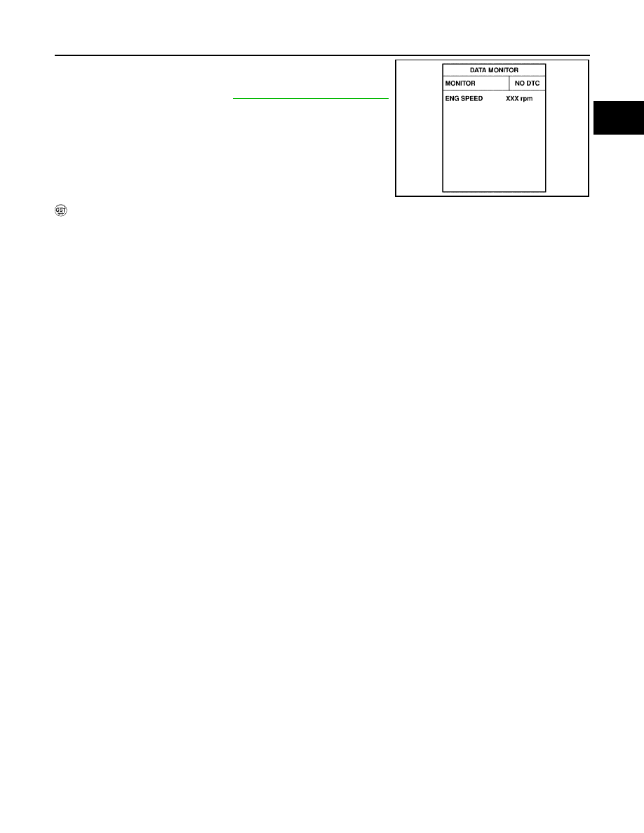
Select “DATA MONITOR” mode with CONSULT-II.
3.
Wait at least 10 seconds.
4.
If 1st trip DTC is detected, go to
EC-517, "Diagnostic Procedure"
.
WITH GST
Follow the procedure “WITH CONSULT-II” above.
SEF058Y