Nissan Pathfinder (2006 year). Manual - part 199


  Index      Manuals     Nissan Pathfinder (2006 year) - Service and Repair Manual


Search            copyright infringement  


Content      ..     197      198      199      200     ..


Nissan Pathfinder (2006 year). Manual - part 199


DTC P0456 EVAP CONTROL SYSTEM

EC-451

C

D

E

F

G

H

I

J

K

L

M

A

EC

2006 Pathfinder

7. 

CHECK FOR EVAP LEAK

 Without CONSULT-II

1.

Turn ignition switch OFF.

2.

Apply 12 volts DC to EVAP canister vent control valve. The
valve will close. (Continue to apply 12 volts until the end of test.)

3.

Pressurize the EVAP line using pressure pump with 1.3 to 2.7
kPa (10 to 20 mmHg, 0.39 to 0.79 inHg), then remove pump and
EVAP service port adapter.

CAUTION:

Never use compressed air or a high pressure pump.

Do not exceed 4.12 kPa (0.042 kg/cm

2

 , 0.6 psi) of pres-

sure in the system.

4.

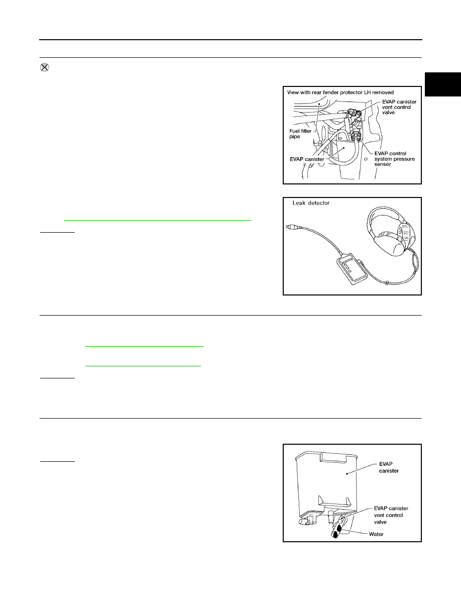
Using EVAP leak detector, locate the EVAP leak. For the leak
detector, refer to the instruction manual for more details. Refer
to 

EC-33, "EVAPORATIVE EMISSION LINE DRAWING"

 .

OK or NG

OK

>> GO TO 8.

NG

>> Repair or replace.

8. 

CHECK EVAP CANISTER VENT CONTROL VALVE

Check the following.

EVAP canister vent control valve is installed properly.
Refer to 

EC-36, "Removal and Installation"

 .

EVAP canister vent control valve.
Refer to 

EC-414, "Component Inspection"

 .

OK or NG

OK

>> GO TO 9.

NG

>> Repair or replace EVAP canister vent control valve and O-ring.

9. 

CHECK IF EVAP CANISTER SATURATED WITH WATER

1.

Remove EVAP canister with EVAP canister vent control valve and EVAP control system pressure sensor
attached.

2.

Does water drain from the EVAP canister?

Yes or No

Yes

>> GO TO 10.

No (With CONSULT-II)>>GO TO 12.
No (Without CONSULT-II)>>GO TO 13.

BBIA0551E

SEF200U

BBIA0558E

EC-452

DTC P0456 EVAP CONTROL SYSTEM

2006 Pathfinder

10. 

CHECK EVAP CANISTER

Weigh the EVAP canister with the EVAP canister vent control valve and EVAP control system pressure sensor
attached.
The weight should be less than 2.0 kg (4.4 lb).

OK or NG

OK (With CONSULT-II)>>GO TO 12.
OK (Without CONSULT-II)>>GO TO 13.
NG

>> GO TO 11.

11. 

DETECT MALFUNCTIONING PART

Check the following.

EVAP canister for damage

EVAP hose between EVAP canister and vehicle frame for clogging or poor connection

>> Repair hose or replace EVAP canister.

12. 

CHECK EVAP CANISTER PURGE VOLUME CONTROL SOLENOID VALVE OPERATION

 With CONSULT-II

1.

Disconnect vacuum hose to EVAP canister purge volume control solenoid valve at EVAP service port.

2.

Start engine.

3.

Perform “PURG VOL CONT/V” in “ACTIVE TEST” mode.

4.

Touch “Qu” on CONSULT-II screen to increase “PURG VOL
CONT/V” opening to 100%.

5.

Check vacuum hose for vacuum when revving engine up to
2,000 rpm.

OK or NG

OK

>> GO TO 16.

NG

>> GO TO 14.

13. 

CHECK EVAP CANISTER PURGE VOLUME CONTROL SOLENOID VALVE OPERATION

 Without CONSULT-II

1.

Start engine and warm it up to normal operating temperature.

2.

Stop engine.

3.

Disconnect vacuum hose to EVAP canister purge volume control solenoid valve at EVAP service port.

4.

Start engine and let it idle for at least 80 seconds.

5.

Check vacuum hose for vacuum when revving engine up to 2,000 rpm.

OK or NG

OK

>> GO TO 15.

NG

>> GO TO 14.

14. 

CHECK VACUUM HOSE

Check vacuum hoses for clogging or disconnection. Refer to 

EC-101, "Vacuum Hose Drawing"

 .

OK or NG

OK

>> GO TO 15.

NG

>> Repair or reconnect the hose.

PBIB1678E

Vacuum should exist.

DTC P0456 EVAP CONTROL SYSTEM

EC-453

C

D

E

F

G

H

I

J

K

L

M

A

EC

2006 Pathfinder

15. 

CHECK EVAP CANISTER PURGE VOLUME CONTROL SOLENOID VALVE

Refer to 

EC-407, "Component Inspection"

 .

OK or NG

OK

>> GO TO 16.

NG

>> Replace EVAP canister purge volume control solenoid valve.

16. 

CHECK FUEL TANK TEMPERATURE SENSOR

Refer to 

EC-333, "Component Inspection"

 .

OK or NG

OK

>> GO TO 17.

NG

>> Replace fuel level sensor unit.

17. 

CHECK EVAP CONTROL SYSTEM PRESSURE SENSOR

Refer to 

EC-430, "Component Inspection"

 .

OK or NG

OK

>> GO TO 18.

NG

>> Replace EVAP control system pressure sensor.

18. 

CHECK EVAP PURGE LINE

Check EVAP purge line (pipe, rubber tube, fuel tank and EVAP canister) for cracks or improper connection.
Refer to 

EC-33, "EVAPORATIVE EMISSION LINE DRAWING"

 .

OK or NG

OK

>> GO TO 19.

NG

>> Repair or reconnect the hose.

19. 

CLEAN EVAP PURGE LINE

Clean EVAP purge line (pipe and rubber tube) using air blower.

>> GO TO 20.

20. 

CHECK EVAP/ORVR LINE

Check EVAP/ORVR line between EVAP canister and fuel tank for clogging, kink, looseness and improper con-
nection. For location, refer to 

EC-39, "ON BOARD REFUELING VAPOR RECOVERY (ORVR)"

 .

OK or NG

OK

>> GO TO 21.

NG

>> Repair or replace hoses and tubes.

21. 

CHECK RECIRCULATION LINE

Check recirculation line between filler neck tube and fuel tank for clogging, kink, cracks, looseness and
improper connection.

OK or NG

OK

>> GO TO 22.

NG

>> Repair or replace hose, tube or filler neck tube.

22. 

CHECK REFUELING EVAP VAPOR CUT VALVE

Refer to 

EC-42, "Component Inspection"

 .

OK or NG

OK

>> GO TO 23.

NG

>> Replace refueling EVAP vapor cut valve with fuel tank. 

EC-454

DTC P0456 EVAP CONTROL SYSTEM

2006 Pathfinder

23. 

CHECK FUEL LEVEL SENSOR

Refer to 

DI-23, "FUEL LEVEL SENSOR UNIT"

 .

OK or NG

OK

>> GO TO 24.

NG

>> Replace fuel level sensor unit.

24. 

CHECK INTERMITTENT INCIDENT

Refer to 

EC-144, "TROUBLE DIAGNOSIS FOR INTERMITTENT INCIDENT"

 .

>> INSPECTION END

DTC P0460 FUEL LEVEL SENSOR

EC-455

C

D

E

F

G

H

I

J

K

L

M

A

EC

2006 Pathfinder

DTC P0460 FUEL LEVEL SENSOR

PFP:25060

Component Description

UBS00KAC

The fuel level sensor is mounted in the fuel level sensor unit. The
sensor detects a fuel level in the fuel tank and transmits a signal to
the combination meter. The combination meter sends the fuel level
sensor signal to the ECM through CAN communication line.
It consists of two parts, one is mechanical float and the other is vari-
able resistor. Fuel level sensor output voltage changes depending on
the movement of the fuel mechanical float.

On Board Diagnosis Logic

UBS00KAD

NOTE:

If DTC P0460 is displayed with DTC U1000 or U1001, first perform the trouble diagnosis for DTC
U1000, U1001.
 Refer to 

EC-153, "DTC U1000, U1001 CAN COMMUNICATION LINE"

 .

If DTC P0460 is displayed with DTC U1010, first perform the trouble diagnosis for DTC U1010.
Refer to 

EC-156, "DTC U1010 CAN COMMUNICATION"

 .

When the vehicle is parked, naturally the fuel level in the fuel tank is stable. It means that output signal of the
fuel level sensor does not change. If ECM senses sloshing signal from the sensor, fuel level sensor malfunc-
tion is detected.

DTC Confirmation Procedure

UBS00KAE

NOTE:
If DTC Confirmation Procedure has been previously conducted, always turn ignition switch OFF and wait at
least 10 seconds before conducting the next test.

 WITH CONSULT-II

1.

Turn ignition switch ON.

2.

Select “DATA MONITOR” mode with CONSULT-II.

3.

Start engine and wait maximum of 2 consecutive minutes.

4.

If 1st trip DTC is detected, go to 

EC-456, "Diagnostic Procedure"

.

 WITH GST

Follow the procedure “WITH CONSULT-II” above.

BBIA0529E

DTC No.

Trouble diagnosis name

DTC detecting condition

Possible cause

P0460
0460

Fuel level sensor circuit 
noise

Even though the vehicle is parked, a signal 
being varied is sent from the fuel level sensor 
to ECM.

Harness or connectors
(The CAN communication line is open or 
shorted)

Harness or connectors
(The sensor circuit is open or shorted)

Combination meter

Fuel level sensor

SEF195Y

EC-456

DTC P0460 FUEL LEVEL SENSOR

2006 Pathfinder

Diagnostic Procedure

UBS00KAF

1. 

CHECK COMBINATION METER FUNCTION

Refer to 

DI-4, "COMBINATION METERS"

 .

OK or NG

OK

>> GO TO 2.

NG

>> Go to 

DI-23, "Fuel Level Sensor Unit Inspection"

 .

2. 

CHECK INTERMITTENT INCIDENT

Refer to 

EC-144, "TROUBLE DIAGNOSIS FOR INTERMITTENT INCIDENT"

 .

>> INSPECTION END

Removal and Installation

UBS00KAG

FUEL LEVEL SENSOR

Refer to 

FL-6, "FUEL LEVEL SENSOR UNIT, FUEL FILTER AND FUEL PUMP ASSEMBLY"

 .

DTC P0461 FUEL LEVEL SENSOR

EC-457

C

D

E

F

G

H

I

J

K

L

M

A

EC

2006 Pathfinder

DTC P0461 FUEL LEVEL SENSOR

PFP:25060

Component Description

UBS00KAH

The fuel level sensor is mounted in the fuel level sensor unit. The
sensor detects a fuel level in the fuel tank and transmits a signal to
the combination meter. The combination meter sends the fuel level
sensor signal to the ECM through CAN communication line.
It consists of two parts, one is mechanical float and the other is vari-
able resistor. Fuel level sensor output voltage changes depending on
the movement of the fuel mechanical float.

On Board Diagnosis Logic

UBS00KAI

NOTE:

If DTC P0461 is displayed with DTC U1000 or U1001, first perform the trouble diagnosis for DTC
U1000, U1001. Refer to 

EC-153, "DTC U1000, U1001 CAN COMMUNICATION LINE"

 .

If DTC P0461 is displayed with DTC U1010, first perform the trouble diagnosis for DTC U1010.
Refer to 

EC-156, "DTC U1010 CAN COMMUNICATION"

 .

Driving long distances naturally affect fuel gauge level.
This diagnosis detects the fuel gauge malfunction of the gauge not moving even after a long distance has
been driven.

Overall Function Check

UBS00KAJ

Use this procedure to check the overall function of the fuel level sensor function. During this check, a 1st trip
DTC might not be confirmed.

WARNING:

When performing following procedure, be sure to observe the handling of the fuel. Refer to 

FL-11,

"FUEL TANK"

 .

TESTING CONDITION:
Before starting overall function check, preparation of draining fuel and refilling fuel is required.

 WITH CONSULT-II

NOTE:
Start from step 10, if it is possible to confirm that the fuel cannot be drained by 30   (7-7/8 US gal, 6-5/
8 Imp gal) in advance.

1.

Prepare a fuel container and a spare hose.

2.

Release fuel pressure from fuel line, refer to 

EC-79, "FUEL PRESSURE RELEASE"

 .

3.

Remove the fuel feed hose on the fuel level sensor unit.

4.

Connect a spare fuel hose where the fuel feed hose was removed.

5.

Turn ignition switch OFF and wait at least 10 seconds then turn ON.

6.

Select “FUEL LEVEL SE” in “DATA MONITOR” mode with CONSULT-II.

BBIA0529E

DTC No.

Trouble diagnosis name

DTC detecting condition

Possible cause

P0461
0461

Fuel level sensor circuit 
range/performance

The output signal of the fuel level sensor does 
not change within the specified range even 
though the vehicle has been driven a long dis-
tance.

Harness or connectors
(The CAN communication line is open or 
shorted)

Harness or connectors
(The sensor circuit is open or shorted)

Combination meter

Fuel level sensor

EC-458

DTC P0461 FUEL LEVEL SENSOR

2006 Pathfinder

7.

Check “FUEL LEVEL SE” output voltage and note it.

8.

Select “FUEL PUMP” in “ACTIVE TEST” mode with CONSULT-
II.

9.

Touch ON and drain fuel approximately 30   (7-7/8 US gal, 6-5/
8 Imp gal) and stop it.

10. Check “FUEL LEVEL SE” output voltage and note it.

11. Fill fuel into the fuel tank for 30   (7-7/8 US gal, 6-5/8 Imp gal).

12. Check “FUEL LEVEL SE” output voltage and note it.

13. Confirm whether the voltage changes more than 0.03V during

step 7 to 10 and 10 to 12.
If NG, go to 

EC-458, "Diagnostic Procedure"

 .

 WITH GST

NOTE:
Start from step 8, if it is possible to confirm that the fuel cannot be drained by 30   (7-7/8 US gal, 6-5/8
Imp gal) in advance.
1.

Prepare a fuel container and a spare hose.

2.

Release fuel pressure from fuel line. Refer to 

EC-79, "FUEL PRESSURE RELEASE"

 .

3.

Remove the fuel feed hose on the fuel level sensor unit.

4.

Connect a spare fuel hose where the fuel feed hose was removed.

5.

Turn ignition switch ON.

6.

Drain fuel by 30   (7-7/8 US gal, 6-5/8 Imp gal) from the fuel tank using proper equipment.

7.

Confirm that the fuel gauge indication varies.

8.

Fill fuel into the fuel tank for 30   (7-7/8 US gal, 6-5/8 Imp gal).

9.

Confirm that the fuel gauge indication varies.

10. If NG, go to 

EC-458, "Diagnostic Procedure"

 .

Diagnostic Procedure

UBS00KAK

1. 

CHECK COMBINATION METER FUNCTION

Refer to 

DI-4, "COMBINATION METERS"

 .

OK or NG

OK

>> GO TO 2.

NG

>> Go to 

DI-23, "Fuel Level Sensor Unit Inspection"

 .

2. 

CHECK INTERMITTENT INCIDENT

Refer to 

EC-144, "TROUBLE DIAGNOSIS FOR INTERMITTENT INCIDENT"

 .

>> INSPECTION END

Removal and Installation

UBS00KAL

FUEL LEVEL SENSOR

Refer to 

FL-6, "FUEL LEVEL SENSOR UNIT, FUEL FILTER AND FUEL PUMP ASSEMBLY"

 .

SEF195Y


Content      ..     197      198      199      200     ..