Nissan Pathfinder (2006 year). Manual - part 180


  Index      Manuals     Nissan Pathfinder (2006 year) - Service and Repair Manual


Search            copyright infringement  


Content      ..     178      179      180      181     ..


Nissan Pathfinder (2006 year). Manual - part 180


DTC P0139, P0159 HO2S2

EC-299

C

D

E

F

G

H

I

J

K

L

M

A

EC

2006 Pathfinder

Specification data are reference values and are measured between each terminal and ground.

CAUTION:

Do not use ECM ground terminals when measuring input/output voltage. Doing so may result in dam-
age to the ECM's transistor. Use a ground other than ECM terminals, such as the ground.

Diagnostic Procedure

UBS00K77

1. 

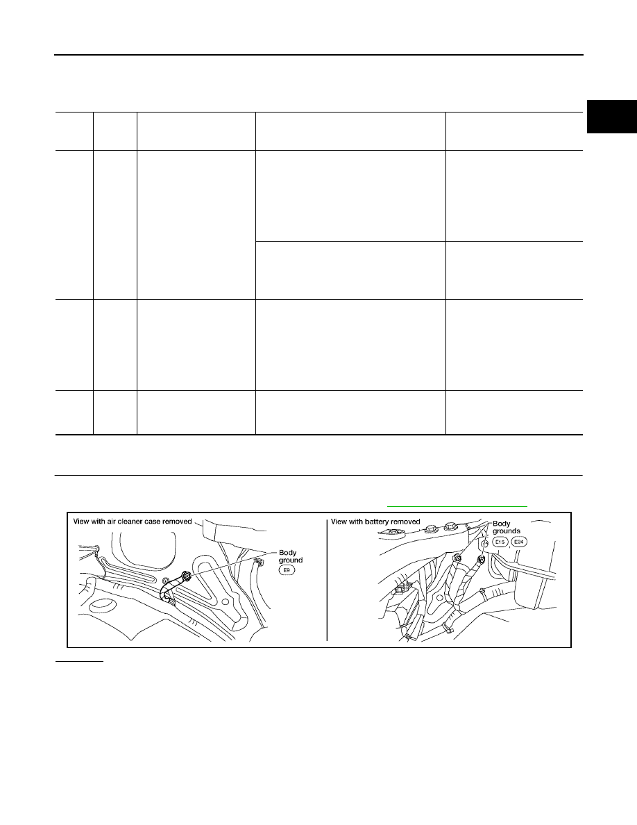
CHECK GROUND CONNECTIONS

1.

Turn ignition switch OFF.

2.

Loosen and retighten three ground screws on the body. Refer to 

EC-151, "Ground Inspection"

 .

OK or NG

OK

>> GO TO 2.

NG

>> Repair or replace ground connections.

TER-

MINAL 

NO.

WIRE 

COLOR

ITEM

CONDITION

DATA (DC Voltage)

6

R

Heated oxygen sensor 2 
heater (Bank 2)

[Engine is running]

Engine speed: Below 3,600 rpm after the 
following conditions are met

Engine: After warming up

Keeping the engine speed between 3,500 
and 4,000 rpm for 1 minute and at idle for 1 
minute under no load

0 - 1.0V

[Ignition switch: ON]

Engine: Stopped

[Engine is running]

Engine speed: Above 3,600 rpm

BATTERY VOLTAGE
(11 - 14V)

55

G

Heated oxygen sensor 2 
(Bank 2)

[Engine is running]

Revving engine from idle to 3,000 rpm 
quickly after the following conditions are met

Engine: After warming up

Keeping the engine speed between 3,500 
and 4,000 rpm for 1 minute and at idle for 1 
minute under no load

0 - Approximately 1.0V

78

GR

Sensor ground
(Heated oxygen sensor 2)

[Engine is running]

Warm-up condition

Idle speed

Approximately 0V

BBIA0539E

EC-300

DTC P0139, P0159 HO2S2

2006 Pathfinder

2. 

CLEAR THE SELF-LEARNING DATA

 With CONSULT-II

1.

Start engine and warm it up to normal operating temperature.

2.

Select “SELF-LEARNING CONT” in “WORK SUPPORT” mode
with CONSULT-II.

3.

Clear the self-learning control coefficient by touching “CLEAR”.

4.

Run engine for at least 10 minutes at idle speed.
Is the 1st trip DTC P0171, P0172, P0174 or P0175 detected?
Is it difficult to start engine?

 Without CONSULT-II

1.

Start engine and warm it up to normal operating temperature.

2.

Turn ignition switch OFF.

3.

Disconnect mass air flow sensor harness connector, and restart
and run engine for at least 5 seconds at idle speed.

4.

Stop engine and reconnect mass air flow sensor harness con-
nector.

5.

Make sure DTC P0102 is displayed.

6.

Erase the DTC memory. Refer to 

EC-60, "HOW TO ERASE

EMISSION-RELATED DIAGNOSTIC INFORMATION"

 .

7.

Make sure DTC P0000 is displayed.

8.

Run engine for at least 10 minutes at idle speed.
Is the 1st trip DTC P0171, P0172, P0174 or P0175 detected?
Is it difficult to start engine?

Yes or No

Yes

>> Perform trouble diagnosis for DTC P0171, P0174 or P0172, P0175. Refer to 

EC-305, "DTC

P0171, P0174 FUEL INJECTION SYSTEM FUNCTION"

   or 

EC-317, "DTC P0172, P0175 FUEL

INJECTION SYSTEM FUNCTION"

 .

No

>> GO TO 3.

SEF968Y

BBIA0541E

DTC P0139, P0159 HO2S2

EC-301

C

D

E

F

G

H

I

J

K

L

M

A

EC

2006 Pathfinder

3. 

CHECK HO2S2 GROUND CIRCUIT FOR OPEN AND SHORT

1.

Turn ignition switch OFF.

2.

Disconnect heated oxygen sensor 2 harness connector.

3.

Disconnect ECM harness connector.

4.

Check harness continuity between HO2S2 terminal 4 and ECM terminal 78.
Refer to Wiring Diagram.

5.

Also check harness for short to ground and short to power.

OK or NG

OK

>> GO TO 4.

NG

>> Repair open circuit or short to ground or short to power in harness or connectors.

Continuity should exist.

BBIA0540E

EC-302

DTC P0139, P0159 HO2S2

2006 Pathfinder

4. 

CHECK HO2S2 INPUT SIGNAL CIRCUIT FOR OPEN AND SHORT

1.

Check harness continuity between ECM terminal and HO2S2 terminal as follows.
Refer to Wiring Diagram.

2.

Check harness continuity between the following terminals and ground.
Refer to Wiring Diagram.

3.

Also check harness for short to power.

OK or NG

OK

>> GO TO 5.

NG

>> Repair open circuit or short to ground or short to power in harness or connectors.

5. 

CHECK HEATED OXYGEN SENSOR 2

Refer to 

EC-302, "Component Inspection"

 .

OK or NG

OK

>> GO TO 6.

NG

>> Replace malfunctioning heated oxygen sensor 2.

6. 

CHECK INTERMITTENT INCIDENT

Refer to 

EC-144, "TROUBLE DIAGNOSIS FOR INTERMITTENT INCIDENT"

 .

>> INSPECTION END

Component Inspection

UBS00K78

HEATED OXYGEN SENSOR 2

 With CONSULT-II

1.

Turn ignition switch ON and select “DATA MONITOR” mode with
CONSULT-II.

2.

Start engine and warm it up to the normal operating tempera-
ture.

3.

Turn ignition switch OFF and wait at least 10 seconds.

4.

Start engine and keep the engine speed between 3,500 and
4,000 rpm for at least 1 minute under no load.

5.

Let engine idle for 1 minute.

DTC

Terminals

Bank

ECM

Sensor

P0139

74

1

1

P0159

55

1

2

Continuity should exist.

DTC

Terminals

Bank

ECM

Sensor

P0139

74

1

1

P0159

55

1

2

Continuity should not exist.

SEF174Y

DTC P0139, P0159 HO2S2

EC-303

C

D

E

F

G

H

I

J

K

L

M

A

EC

2006 Pathfinder

6.

Select “FUEL INJECTION” in “ACTIVE TEST” mode, and select
“HO2S2 (B1)/(B2)” as the monitor item with CONSULT-II.

7.

Check “HO2S2 (B1)/(B2)” at idle speed when adjusting “FUEL INJECTION” to 

±

25%.

“HO2S2 (B1)/(B2)” should be above 0.68V at least once when the “FUEL INJECTION” is +25%.
“HO2S2 (B1)/(B2)” should be below 0.18V at least once when the “FUEL INJECTION” is 

25%.

CAUTION:

Discard any heated oxygen sensor which has been dropped from a height of more than 0.5 m (19.7
in) onto a hard surface such as a concrete floor; use a new one.

Before installing new oxygen sensor, clean exhaust system threads using Oxygen Sensor Thread
Cleaner tool J-43897-18 or J-43897-12 and approved anti-seize lubricant.

 Without CONSULT-II

1.

Start engine and warm it up to the normal operating temperature.

2.

Turn ignition switch OFF and wait at least 10 seconds.

3.

Start engine and keep the engine speed between 3,500 and 4,000 rpm for at least 1 minute under no load.

4.

Let engine idle for 1 minute.

5.

Set voltmeter probes between ECM terminal 74 [HO2S2 (B1) signal] or 55 [HO2S2 (B2) signal] and
ground.

6.

Check the voltage when revving up to 4,000 rpm under no load
at least 10 times.
(Depress and release accelerator pedal as soon as possible.)
The voltage should be above 0.68V at least once during this
procedure.
If the voltage is above 0.68V at step 6, step 7 is not neces-
sary.

7.

Keep vehicle at idling for 10 minutes, then check voltage. Or
check the voltage when coasting from 80 km/h (50 MPH) in D
position with “OD” OFF.
The voltage should be below 0.18V at least once during this
procedure.

8.

If NG, replace heated oxygen sensor 2.

CAUTION:

Discard any heated oxygen sensor which has been dropped from a height of more than 0.5 m (19.7
in) onto a hard surface such as a concrete floor; use a new one.

Before installing new oxygen sensor, clean exhaust system threads using Oxygen Sensor Thread
Cleaner tool J-43897-18 or J-43897-12 and approved anti-seize lubricant.

PBIB1672E

PBIB2534E

PBIB1607E

EC-304

DTC P0139, P0159 HO2S2

2006 Pathfinder

Removal and Installation

UBS00K79

HEATED OXYGEN SENSOR 2

Refer to 

EM-22, "EXHAUST MANIFOLD AND THREE WAY CATALYST"

 .

DTC P0171, P0174 FUEL INJECTION SYSTEM FUNCTION

EC-305

C

D

E

F

G

H

I

J

K

L

M

A

EC

2006 Pathfinder

DTC P0171, P0174 FUEL INJECTION SYSTEM FUNCTION

PFP:16600

On Board Diagnosis Logic

UBS00K7A

With the Air-Fuel Mixture Ratio Self-Learning Control, the actual mixture ratio can be brought closely to the
theoretical mixture ratio based on the mixture ratio feedback signal from the air fuel ratio (A/F) sensor 1. The
ECM calculates the necessary compensation to correct the offset between the actual and the theoretical
ratios.
In case the amount of the compensation value is extremely large (the actual mixture ratio is too lean.), the
ECM judges the condition as the fuel injection system malfunction and lights up the MIL (2 trip detection logic).

DTC Confirmation Procedure

UBS00K7B

NOTE:
If DTC Confirmation Procedure has been previously conducted, always turn ignition switch OFF and wait at
least 10 seconds before conducting the next test.

 WITH CONSULT-II

1.

Start engine and warm it up to normal operating temperature.

2.

Turn ignition switch OFF and wait at least 10 seconds.

3.

Turn ignition switch ON and select “SELF-LEARNING CONT” in “WORK SUPPORT” mode with CON-
SULT-II.

4.

Clear the self-learning control coefficient by touching “CLEAR”.

5.

Select “DATA MONITOR” mode with CONSULT-II.

6.

Start engine again and let it idle for at least 10 minutes.
The 1st trip DTC P0171 or P0174 should be detected at this
stage, if a malfunction exists. If so, go to 

EC-311, "Diagnostic

Procedure"

 .

NOTE:
If 1st trip DTC is not detected during above procedure, perform-
ing the following procedure is advised.

a.

Turn ignition switch OFF and wait at least 10 seconds.

b.

Start engine and drive the vehicle under the similar conditions to
(1st trip) Freeze Frame Data for 10 minutes. Refer to the table below.
Hold the accelerator pedal as steady as possible.

The similar conditions to (1st trip) Freeze Frame Data means the vehicle operation that the following con-
ditions should be satisfied at the same time.

Sensor

Input signal to ECM

ECM function

Actuator

A/F sensor 1

Density of oxygen in exhaust gas
(Mixture ratio feedback signal)

Fuel injection 
control

Fuel injector

DTC No.

Trouble diagnosis 

name

DTC detecting condition

Possible cause

P0171
0171
(Bank 1)

Fuel injection system 
too lean

Fuel injection system does not operate properly.

The amount of mixture ratio compensation is too 
large. (The mixture ratio is too lean.)

Intake air leaks

Air fuel ratio (A/F) sensor 1

Fuel injector

Exhaust gas leaks

Incorrect fuel pressure

Lack of fuel

Mass air flow sensor

Incorrect PCV hose connection

P0174
0174
(Bank 2)

SEF968Y

Engine speed

Engine speed in the freeze frame data 

±

 400 rpm

Vehicle speed

Vehicle speed in the freeze frame data 

±

 10 km/h (6 MPH)

EC-306

DTC P0171, P0174 FUEL INJECTION SYSTEM FUNCTION

2006 Pathfinder

7.

If it is difficult to start engine at step 6, the fuel injection system has a malfunction, too.

8.

Crank engine while depressing accelerator pedal. If engine starts, go to 

EC-311, "Diagnostic Procedure"

 .

If engine does not start, check exhaust and intake air leak visually.

 WITH GST

1.

Start engine and warm it up to normal operating temperature.

2.

Turn ignition switch OFF and wait at least 10 seconds.

3.

Disconnect mass air flow sensor harness connector.

4.

Restart engine and let it idle for at least 5 seconds.

5.

Stop engine and reconnect mass air flow sensor harness con-
nector.

6.

Select Service $03 with GST. Make sure DTC P0102 is
detected.

7.

Select Service $04 with GST and erase the DTC P0102.

8.

Start engine again and let it idle for at least 10 minutes.

9.

Select Service $07 with GST. The 1st trip DTC P0171 or P0174
should be detected at this stage, if a malfunction exists. If so, go
to 

EC-311, "Diagnostic Procedure"

 .

NOTE:
If 1st trip DTC is not detected during above procedure, performing the following procedure is advised.

a.

Turn ignition switch OFF and wait at least 10 seconds.

b.

Start engine and drive the vehicle under the similar conditions to (1st trip) Freeze Frame Data for 10 min-
utes. Refer to the table below.
Hold the accelerator pedal as steady as possible.

The similar conditions to (1st trip) Freeze Frame Data means the vehicle operation that the following con-
ditions should be satisfied at the same time.

10. If it is difficult to start engine at step 8, the fuel injection system has a malfunction.
11. Crank engine while depressing accelerator pedal. If engine starts, go to 

EC-311, "Diagnostic Procedure"

 .

If engine does not start, check exhaust and intake air leak visually.

Engine coolant temperature 
(T) condition

When the freeze frame data shows lower than 70 

°

C (158 

°

F),

T should be lower than 70 

°

C (158 

°

F).

When the freeze frame data shows higher than or equal to 70 

°

C (158 

°

F),

T should be higher than or equal to 70 

°

C (158 

°

F).

BBIA0541E

Engine speed

Engine speed in the freeze frame data 

±

 400 rpm

Vehicle speed

Vehicle speed in the freeze frame data 

±

 10 km/h (6 MPH)

Engine coolant temperature 
(T) condition

When the freeze frame data shows lower than 70 

°

C (158 

°

F),

T should be lower than 70 

°

C (158 

°

F).

When the freeze frame data shows higher than or equal to 70 

°

C (158 

°

F),

T should be higher than or equal to 70 

°

C (158 

°

F).


Content      ..     178      179      180      181     ..