Nissan Pathfinder (2006 year). Manual - part 171


  Index      Manuals     Nissan Pathfinder (2006 year) - Service and Repair Manual


Search            copyright infringement  


Content      ..     169      170      171      172     ..


Nissan Pathfinder (2006 year). Manual - part 171


DTC P0130, P0150 A/F SENSOR 1

EC-227

C

D

E

F

G

H

I

J

K

L

M

A

EC

2006 Pathfinder

DTC P0130, P0150 A/F SENSOR 1

PFP:22693

Component Description

UBS00KEU

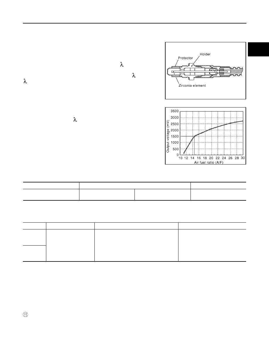
The air fuel ratio (A/F) sensor 1 is a planar dual-cell limit current sen-
sor. The sensor element of the A/F sensor 1 is the combination of a
Nernst concentration cell (sensor cell) with an oxygen-pump cell,
which transports ions. It has a heater in the element.
The sensor is capable of precise measurement   = 1, but also in the
lean and rich range. Together with its control electronics, the sensor
outputs a clear, continuous signal throughout a wide   range (0.7 <

 < air).

The exhaust gas components diffuse through the diffusion gap at the
electrode of the oxygen pump and Nernst concentration cell, where
they are brought to thermodynamic balance.

An electronic circuit controls the pump current through the oxygen-
pump cell so that the composition of the exhaust gas in the diffusion
gap remains constant at   = 1. Therefore, the A/F sensor 1 is able to
indicate air/fuel ratio by this pumping of current. In addition, a heater
is integrated in the sensor to ensure the required operating tempera-
ture of 700 - 800

°

C (1,292 - 1,472

°

F).

CONSULT-II Reference Value in Data Monitor Mode

UBS00KEV

Specification data are reference values.

On Board Diagnosis Logic

UBS00KEW

To judge the malfunction, the diagnosis checks that the A/F signal computed by ECM from the A/F sensor 1
signal fluctuates according to fuel feedback control.

DTC Confirmation Procedure

UBS00KEX

CAUTION:

Always drive vehicle at a safe speed.
NOTE:
If DTC Confirmation Procedure has been previously conducted, always turn ignition switch OFF and wait at
least 10 seconds before conducting the next test.
TESTING CONDITION:
Before performing the following procedure, confirm that battery voltage is more than 11V at idle.

 WITH CONSULT-II

1.

Start engine and warm it up to normal operating temperature.

2.

Select “A/F SEN1 (B1)” or “A/F SEN1 (B2)” in “DATA MONITOR” mode with CONSULT-II.

3.

Check “A/F SEN1 (B1)” or “A/F SEN1 (B2)” indication.

SEF579Z

SEF580Z

MONITOR ITEM

CONDITION

SPECIFICATION

A/F SEN1 (B1)
A/F SEN1 (B2)

Engine: After warming up

Maintaining engine speed at 
2,000 rpm

Fluctuates around 1.5V

DTC No.

Trouble diagnosis name

DTC detecting condition

Possible Cause

P0130
0130
(Bank 1)

Air fuel ratio (A/F) sensor 1 
circuit 

The A/F signal computed by ECM from the A/
F sensor 1 signal is constantly approx. 1.5V.

Harness or connectors
(The A/F sensor 1 circuit is open or 
shorted.)

A/F sensor 1

P0150
0150
(Bank 2)

EC-228

DTC P0130, P0150 A/F SENSOR 1

2006 Pathfinder

If the indication is constantly approx. 1.5V and does not fluctuates, go to 

EC-233, "Diagnostic Procedure"

 .

If the indication fluctuates around 1.5V, go to next step.

4.

Select “A/F SEN1 (B1) P1276” (for DTC P0130) or “A/F SEN1 (B2) P1286” (for DTC P0150) of “A/F
SEN1” in “DTC WORK SUPPORT” mode with CONSULT-II.

5.

Touch “START”.

6.

When the following conditions are met, “TESTING” will be dis-
played on the CONSULT-II screen.

If “TESTING” is not displayed after 20 seconds, retry from
step 2.

7.

Release accelerator pedal fully.

NOTE:
Never apply brake during releasing the accelerator pedal.

8.

Make sure that “TESTING” changes to “COMPLETED”.
If “TESTING” changed to “OUT OF CONDITION”, retry from
step 6.

9.

Make sure that “OK” is displayed after touching “SELF-DIAG
RESULT”.
If “NG” is displayed, go to 

EC-233, "Diagnostic Procedure"

 .

Overall Function Check

UBS00KEY

Use this procedure to check the overall function of the A/F sensor 1 circuit. During this check, a 1st trip DTC
might not be confirmed.

 WITH GST

1.

Start engine and warm it up to normal operating temperature.

2.

Drive the vehicle at a speed of 80 km/h (50 MPH) for a few minutes in the suitable gear position.

3.

Set D position with “OD” OFF, then release the accelerator pedal fully until the vehicle speed decreases to
50 km/h (30 MPH).

NOTE:
Never apply brake during releasing the accelerator pedal.

4.

Repeat steps 2 and 3 for five times.

5.

Stop the vehicle and turn ignition switch OFF.

6.

Wait at least 10 seconds and restart engine.

7.

Repeat steps 2 and 3 for five times.

ENG SPEED

1,750 - 3,200 rpm

VHCL SPEED SE

More than 64 km/h (40 MPH)

B/FUEL SCHDL

1.0 - 8.0 msec

Selector lever

D position with “OD” OFF

SEF576Z

SEF577Z

SEF578Z

DTC P0130, P0150 A/F SENSOR 1

EC-229

C

D

E

F

G

H

I

J

K

L

M

A

EC

2006 Pathfinder

8.

Stop the vehicle and connect GST to the vehicle.

9.

Make sure that no DTC is displayed.
If the DTC is displayed, go to 

EC-233, "Diagnostic Procedure"

 .

EC-230

DTC P0130, P0150 A/F SENSOR 1

2006 Pathfinder

Wiring Diagram

UBS00KEZ

BANK 1

BBWA2360E

DTC P0130, P0150 A/F SENSOR 1

EC-231

C

D

E

F

G

H

I

J

K

L

M

A

EC

2006 Pathfinder

Specification data are reference values and are measured between each terminal and ground.
Pulse signal is measured by CONSULT-II.

CAUTION:

Do not use ECM ground terminals when measuring input/output voltage. Doing so may result in dam-
age to the ECM's transistor. Use a ground other than ECM terminals, such as the ground.

: Average voltage for pulse signal (Actual pulse signal can be confirmed by oscilloscope.)

TERMI-

NAL 

NO.

WIRE 

COLOR

ITEM

CONDITION

DATA (DC Voltage)

2

G

A/F sensor 1 heater
(Bank 1)

[Engine is running]

Warm-up condition

Idle speed

Approximately 5V

16

BR

A/F sensor 1 (Bank 1)

[Engine is running]

Warm-up condition

Idle speed

Approximately 3.1V

35

O

Approximately 2.6V

56

LG

Approximately 2.3V

75

P

Approximately 2.3V

PBIB1584E

EC-232

DTC P0130, P0150 A/F SENSOR 1

2006 Pathfinder

BANK 2

BBWA2361E

DTC P0130, P0150 A/F SENSOR 1

EC-233

C

D

E

F

G

H

I

J

K

L

M

A

EC

2006 Pathfinder

Specification data are reference values and are measured between each terminal and ground.
Pulse signal is measured by CONSULT-II.

CAUTION:

Do not use ECM ground terminals when measuring input/output voltage. Doing so may result in dam-
age to the ECM's transistor. Use a ground other than ECM terminals, such as the ground.

: Average voltage for pulse signal (Actual pulse signal can be confirmed by oscilloscope.)

Diagnostic Procedure

UBS00KF0

1. 

CHECK GROUND CONNECTIONS

1.

Turn ignition switch OFF.

2.

Loosen and retighten three ground screws on the body. Refer to 

EC-151, "Ground Inspection"

 .

OK or NG

OK

>> GO TO 2.

NG

>> Repair or replace ground connections.

TERMI-

NAL 

NO.

WIRE 

COLOR

ITEM

CONDITION

DATA (DC Voltage)

24

G

A/F sensor 1 heater
 (Bank 2)

[Engine is running]

Warm-up condition

Idle speed

Approximately 5V

57

GR

A/F sensor 1 (Bank 2)

[Engine is running]

Warm-up condition

Idle speed

Approximately 2.6V

58

O

Approximately 2.3V

76

V

Approximately 3.1V

77

Y

Approximately 2.3V

PBIB1584E

BBIA0539E

EC-234

DTC P0130, P0150 A/F SENSOR 1

2006 Pathfinder

2. 

CHECK AIR FUEL RATIO (A/F) SENSOR 1 POWER SUPPLY CIRCUIT

1.

Disconnect A/F sensor 1 harness connector.

2.

Turn ignition switch ON.

3.

Check voltage between A/F sensor 1 terminal 3 and ground with
CONSULT-II or tester.

OK or NG

OK

>> GO TO 4.

NG

>> GO TO 3.

3. 

DETECT MALFUNCTIONING PART

Check the following.

Harness connectors E5, F14

IPDM E/R connector E119

10A fuse

Harness for open or short between A/F sensor 1 and fuse

>> Repair or replace harness or connectors.

Voltage: Battery voltage

BBIA0544E

PBIB1683E


Content      ..     169      170      171      172     ..