Nissan Pathfinder (2006 year). Manual - part 134


  Index      Manuals     Nissan Pathfinder (2006 year) - Service and Repair Manual


Search            copyright infringement  


Content      ..     132      133      134      135     ..


Nissan Pathfinder (2006 year). Manual - part 134


WATER PUMP

CO-21

C

D

E

F

G

H

I

J

K

L

M

A

CO

2006 Pathfinder

b.

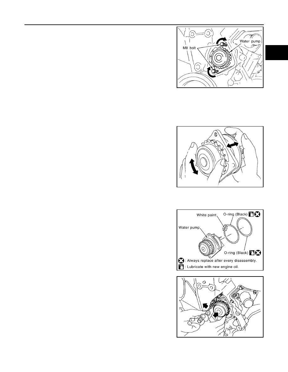
Screw M8 bolts [pitch: 1.25 mm (0.049 in) length: approx. 50
mm (1.97 in)] into water pumps upper and lower bolt holes until
they reach timing chain case. Then, alternately tighten each bolt
for a half turn, and pull out water pump.

CAUTION:

Pull straight out while preventing vane from contacting
socket in installation area.

Remove water pump without causing sprocket to contact
timing chain.

c.

Remove M8 bolts and O-rings from water pump.

CAUTION:

Do not disassemble water pump.

NOTE:
Do not reuse O-rings.

INSPECTION AFTER REMOVAL

Check for badly rusted or corroded water pump body assembly.

Check for rough operation due to excessive end play.

Replace water pump, if necessary.

INSTALLATION

1.

Install new O-rings to water pump.
NOTE:

Apply engine oil to O-rings.

Locate O-ring with white paint mark to engine front side.

2.

 Install water pump.

CAUTION:

Do not allow timing chain case to nip O-rings when install
water pump.

Make sure that timing chain and water pump sprocket are
engaged.

Insert water pump by tightening bolts alternately and evenly.

3.

Install timing chain tensioner (primary) as follows:

JLC357B

SLC943A

PBIC2837E

PBIC1058E

CO-22

WATER PUMP

2006 Pathfinder

a.

Remove dust and foreign material completely from backside of timing chain tensioner (primary) and from
installation area of rear timing chain case.

b.

Turn crankshaft pulley clockwise so that timing chain on the timing chain tensioner (primary) side is loose.

c.

Install timing chain tensioner (primary) with its stopper pin attached.

CAUTION:

Be careful not to drop bolts inside timing chain case.

d.

Remove stopper pin.

e.

Make sure again that timing chain and water pump sprocket are engaged.

4.

Install chain tensioner cover and water pump cover as follows:

a.

Before installing, remove all traces of old liquid gasket from mat-
ing surface of water pump cover and chain tensioner cover
using scraper. Also remove traces of old liquid gasket from the
mating surface of front timing chain case.

b.

Apply a continuous bead of liquid gasket, to mating surface of chain tensioner and water pump cover,
using Tool.

Use Genuine RTV Silicone Sealant or equivalent. Refer to

GI-47, "Recommended Chemical Products and Sealants"

 .

CAUTION:

Attaching should be done within 5 minutes after coating.

c.

Tighten bolts to specified torque. Refer to 

CO-19, "Removal and

Installation"

 .

5.

Refill engine coolant system. Refer to 

MA-14, "REFILLING ENGINE COOLANT"

 .

Apply liquid gasket to the thread of water drain plug (front).
Use Genuine RTV Silicone Sealant or equivalent. Refer to 

GI-47, "Recommended Chemical

Products and Sealants"

 .

6.

Installation of the remaining components is in the reverse order of removal after this step.

After starting engine, let idle for three minutes, then rev engine up to 3,000 rpm under no load to
purge air from the high-pressure chamber of chain tensioner. Engine may produce a rattling
noise. This indicates that air still remains in the chamber and is not a matter of concern.

INSPECTION AFTER INSTALLATION

Check for leaks of engine coolant using tool. Refer to 

CO-9, "CHECKING COOLING SYSTEM FOR

LEAKS"

 .

PBIC2838E

SLC446B

Tool number

: WS39930000 (

)

PBIC2663E

WATER PUMP

CO-23

C

D

E

F

G

H

I

J

K

L

M

A

CO

2006 Pathfinder

Start and warm up engine. Visually check there are no leaks of engine coolant.

CO-24

WATER INLET AND THERMOSTAT ASSEMBLY

2006 Pathfinder

WATER INLET AND THERMOSTAT ASSEMBLY

PFP:21200

Removal and Installation

EBS00QD2

REMOVAL

1.

Completely drain engine coolant. Refer to 

MA-13, "DRAINING ENGINE COOLANT"

 .

CAUTION:

Perform this step when engine is cold.

Do not spill engine coolant on drive belts.

2.

Remove air duct and air cleaner case. Refer to 

EM-16, "Removal and Installation"

 .

3.

Disconnect radiator hose (lower) and oil cooler hose from water inlet and thermostat assembly.

4.

Remove water inlet and thermostat assembly.

CAUTION:

Do not disassemble water inlet and thermostat assembly.
Replace them as a unit, if necessary.

INSPECTION AFTER REMOVAL

1.

Check valve seating condition at ordinary room temperatures. It should seat tightly.

2.

Check valve operation.

If the malfunctioning condition, when valve seating at ordinary
room temperature, or measured values are out of the standard,
replace water inlet and thermostat assembly.

1.

Water inlet and thermostat assembly 2.

Gasket

PBIC2839E

SLC962AB

Thermostat

Standard

Valve opening temperature

80.5 - 83.5

°

C (177 - 182

°

F)

Maximum valve lift

8.6 mm / 95

°

C (0.339 in / 203

°

F)

Valve closing temperature

77

°

C (171

°

F)

SLC949A

WATER INLET AND THERMOSTAT ASSEMBLY

CO-25

C

D

E

F

G

H

I

J

K

L

M

A

CO

2006 Pathfinder

INSTALLATION

Installation is in the reverse order of removal, paying attention to the following.

Be careful not to spill engine coolant over engine room. Use rag to absorb engine coolant.

INSPECTION AFTER INSTALLATION

Check for leaks of engine coolant using tool. Refer to 

CO-9, "CHECKING COOLING SYSTEM FOR

LEAKS"

 .

Start and warm up engine. Visually check there are no leaks of engine coolant.

CO-26

WATER OUTLET AND WATER PIPING

2006 Pathfinder

WATER OUTLET AND WATER PIPING

PFP:11060

Removal and Installation

EBS00QD3

REMOVAL

1.

Completely drain engine coolant. Refer to 

MA-13, "DRAINING ENGINE COOLANT"

 .

CAUTION:

Perform this step when engine is cold.

Do not spill engine coolant on drive belts.

2.

Remove A/T fluid charging pipe Refer to 

AT-246, "TRANSMISSION ASSEMBLY"

 .

3.

Remove the rocker cover (right bank). Refer to 

EM-41, "Removal and Installation"

 .

4.

Remove engine coolant temperature sensor as necessary.

CAUTION:

Be careful not to damage engine coolant temperature sensor.

5.

Remove water outlet, heater pipe, water bypass hoses and water pipe.

INSTALLATION

Installation is in the reverse order of removal, paying attention to the following.

Securely insert each hose, and install clamp at a position where it does not interfere with the pipe bulge.

When inserting water pipe into water outlet, apply neutral detergent to O-ring.

INSPECTION AFTER INSTALLATION

Check for leaks of engine coolant using tool. Refer to 

CO-9, "CHECKING COOLING SYSTEM FOR

LEAKS"

 .

1.

Engine coolant temperature sensor

2.

Washer

3.

Water outlet

4.

Heater hose

5.

O-ring

6.

Water pipe

7.

Water hose

8.

Radiator hose (upper)

9.

Water hose

10. Water hose

11.

Gasket

12.

Heater pipe

13. Heater hose

14.

Gasket

WBIA0615E

WATER OUTLET AND WATER PIPING

CO-27

C

D

E

F

G

H

I

J

K

L

M

A

CO

2006 Pathfinder

Start and warm up engine. Visually check there are no leaks of engine coolant.

CO-28

SERVICE DATA AND SPECIFICATIONS (SDS)

2006 Pathfinder

SERVICE DATA AND SPECIFICATIONS (SDS)

PFP:00100

Standard and Limit

EBS00QD4

ENGINE COOLANT CAPACITY (APPROXIMATE)

Unit: 

 (US gal, Imp gal)

RADIATOR

Unit: kPa (kg/cm

2

 , psi)

THERMOSTAT

Engine coolant capacity (With reservoir tank at 
“MAX” level)

Without rear A/C

10.2 (2-3/4, 2-1/4)

With rear A/C

13.4 (3-1/2, 3.0)

Cap relief pressure

Standard

95 - 125 (0.97 - 1.28, 14 - 18)

Limit

59 (0.6, 9)

Leakage testing pressure

137 (1.4, 20)

Valve opening temperature

80.5 - 83.5

°

C (177 - 182

°

F)

Maximum valve lift

8.6 mm / 95

°

C (0.339 in / 203

°

F)

valve closing temperature

77

°

C (171

°

F)


Content      ..     132      133      134      135     ..