Nissan Pathfinder (2006 year). Manual - part 51
TROUBLE DIAGNOSIS
ATC-73
C
D
E
F
G
H
I
K
L
M
A
B
ATC
2006 Pathfinder
SYSTEM DESCRIPTION
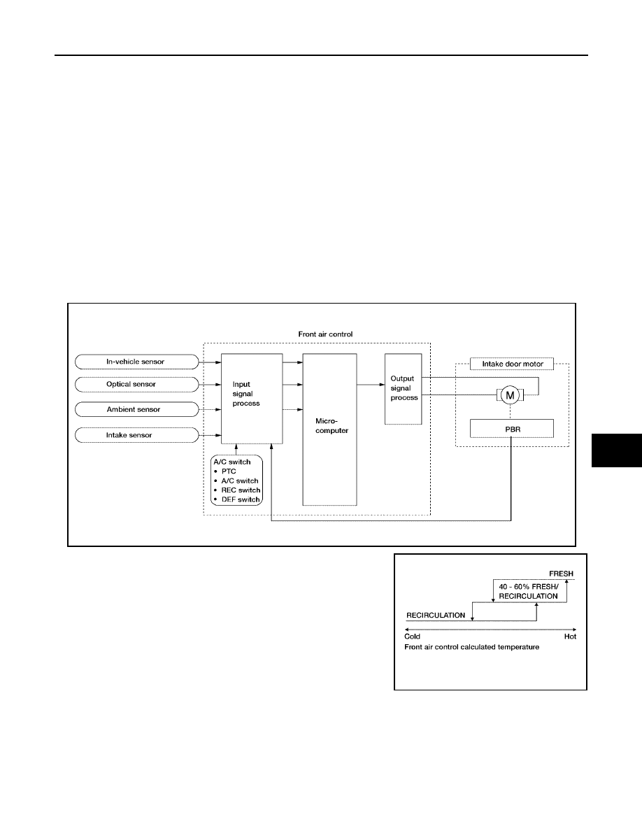
Component Parts
Intake door control system components are:
●
Front air control
●
Intake door motor
●
In-vehicle sensor
●
Ambient sensor
●
Optical sensor
●
Intake sensor
System Operation
The intake door control determines the intake door position based on the position of the recirculation switch.
When the recirculation switch is depressed the intake door motor rotates closing off the fresh air inlet and
recirculating the cabin air. If the recirculation switch is depressed again, the intake door motor rotates in the
opposite direction, again allowing fresh air into the cabin.
In the AUTO mode, the front air control determines the intake door position based on the ambient tempera-
ture, the intake air temperature and the in-vehicle temperature. When the DEFROST, or OFF switches are
pushed or A/C switch is OFF, the front air control sets the intake door at the fresh position.
Intake Door Control Specification
WJIA1352E
WJIA0436E